Do you have a question about the LS ELECTRIC LSLV-S100 Series and is the answer not in the manual?
Explains the meaning of safety symbols used in the manual for quick understanding and reference.
Provides crucial safety guidelines to prevent hazards like electric shock, injury, or death during operation.
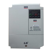
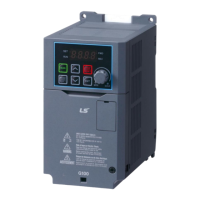
Details on how to identify the S100 inverter model and its specifications from the rating plate.
Illustrations and descriptions of the main components and parts of the inverter models for user familiarity.
Guides on selecting the appropriate installation location, considering environmental conditions and clearances.
Specifies the requirements for power and signal cables, including material, rating, and cross-sectional area.
Provides a step-by-step flowchart for inverter installation and a basic configuration diagram for system setup.
Detailed instructions on how to physically mount the inverter on a wall or inside a panel, including fixing points.
Comprehensive guide on connecting power and control cables, including precautions and specific steps for different models.
Instructions for correctly installing the ground connection for the inverter and motor, specifying grounding classes.
Illustrates the terminal layout and provides descriptions for power terminal connections, emphasizing correct wiring.
Details the layout of control wiring terminals and describes how to connect control cables according to specifications.
Explains how to select PNP (Source) or NPN (Sink) modes for sequence inputs using the control board switch (SW1).
Provides instructions on disabling the built-in EMC filter for power sources with asymmetrical grounding, with model-specific steps.
A comprehensive checklist to verify safe and correct inverter installation, covering location, wiring, and connections.
Step-by-step guide to test the inverter after installation, including power-on, command source selection, and motor operation checks.
Identifies the display and operation keys on the inverter keypad, explaining their part names and functions for user interaction.
Illustrates how to navigate between different display modes (Monitor, Parameter, Trip, Config) using the [Mode] button.
Explains how to navigate through parameter groups and codes using keypad keys for configuration and setup.
Guides on enabling or disabling features by setting or modifying parameter values for different codes using the keypad.
Demonstrates practical examples of configuring common inverter functions like acceleration time and frequency reference.
Details how to monitor output current, fault trips, and other operational parameters using the keypad.
Lists and describes parameters within the Operation group, covering target frequency, acceleration/deceleration times, and command source.
Details parameters for the Drive group, including jump code, torque command, acceleration/deceleration times, and command source settings.
Describes parameters for the Basic Function group, covering auxiliary reference sources and command calculation types.
Lists parameters for the Expanded Function group, including acceleration/deceleration patterns, start/stop modes, and rotation prevention.
Details parameters for the Control Function group, covering carrier frequency, switching mode, and initial excitation settings.
Describes parameters for input terminals, including frequency, torque, voltage, and polarity settings for analog inputs.
Details parameters for output terminals, covering analog output items, gain, bias, filter, and monitoring functions.
Explains communication parameters, including protocol, speed, frame setting, and delay after reception for inverter communication.
Covers parameters for application functions like PID control, reference sources, feedback, and output settings for accurate operation.
Details protection parameters such as load level, open-phase protection, input voltage range, and overload/underload settings.
Provides parameters for configuring a second motor, including acceleration/deceleration times, capacity, and control modes.
Explains parameters for user-defined sequences, including operation commands, loop time, and output address links.
Details parameters for user sequence functions, covering various input/output operations, logic functions, and control blocks.
Lists groups specific to the LCD keypad, including Trip Mode and Config Mode options for parameter management.
Explains how the inverter indicates faults (trips) or issues (warnings) via the keypad display and categorizes fault conditions.
Details common fault trip types, their causes, and recommended remedies for diagnosing and resolving inverter issues.
Addresses troubleshooting steps for faults not classified as trips or warnings, covering parameter issues and motor rotation problems.
Provides guidelines for daily, annual, and bi-annual inspections to ensure the inverter's optimal performance and longevity.
Information on the exchange cycle for major components like cooling fans and capacitors, including symptoms of failure.
Instructions on how to properly store the inverter for extended periods and guidelines for environmentally responsible product disposal.
Detailed tables outlining electrical specifications for applied motors, rated output, and rated input across various models.
Summarizes key control methods, frequency settings, operation types, and functions for the inverter's operation.
Provides dimensional drawings and key measurements (W, H, D) for different inverter models, aiding installation planning.
Lists compatible circuit breakers, leakage breakers, and magnetic contactors recommended for use with the inverter.
Specifies AC input fuses, AC reactors, and DC reactors, including their ratings and compatibility with different inverter models.
Details the terminal screw sizes and recommended torque values for input/output and control circuit terminals for secure connections.
Provides specifications for dynamic braking units and resistors, including UL forms, capacity, and terminal arrangements.
Explains how carrier frequency, input voltage, and ambient temperature affect the inverter's continuous rated current.
Presents graphs and tables showing the heat emission characteristics of inverters based on product capacity.
Details the composition of the remote control loader and cables, and provides instructions for connecting the remote keypad.
Explains the constraints and considerations when applying single-phase power to a three-phase VFD, including DC bus ripple and current distortion.
Discusses necessary derating of output current and horsepower due to DC bus ripple, input current distortion, and the need for reactors.
Specifies the required AC supply voltage ranges and input frequency tolerances for single-phase input to maximize motor power production.
Details the product warranty coverage, duration, and how to obtain warranty service for malfunctions under normal operating conditions.
Outlines conditions under which a service fee will be incurred for malfunctions, including intentional abuse, acts of nature, and unauthorized modifications.
States conformity with essential requirements of EU directives, including EMC and Low Voltage directives, based on applied standards.
Explains the meaning of UL, CE, and EAC marks, indicating compliance with safety and environmental regulations in respective regions.
Provides step-by-step instructions for installing EMI/RFI filters, including filter rating checks, wiring, and mounting procedures.
| Cooling Method | Fan cooling |
|---|---|
| Series | LSLV-S100 |
| Input Frequency | 50/60Hz |
| Output Frequency | 0.1~400Hz |
| Rated Output Current | Varies by model (see individual model specifications) |
| Control Method | V/F Control, Sensorless Vector Control |
| Overload Capacity | 150% for 60 seconds |
| Braking Unit | Built-in |
| Protection Functions | Overcurrent, Overvoltage, Undervoltage, Overheat, Ground fault, Short circuit |
| Communication | RS-485 (Modbus RTU) |
| Operating Temperature | -10°C to +40°C (Non-freezing) |
| Humidity | Less than 95% RH (non-condensing) |
| Altitude | Below 1, 000m |
| Enclosure Rating | IP20 |
| Weight | Depends on model (e.g., 1.5kg to 150kg) |
| Dimensions | Varies by model (see individual model specifications) |
| Input Voltage | 3-phase 200~240VAC, 3-phase 380~480VAC |
| Output Voltage | 3-phase 200~240VAC, 3-phase 380~480VAC (equal to input voltage) |