E1V1 V2 VNV3
E2
Trip relay
Voltage Module
Z3 Z1
Z4 Z2
485+
485-
R11
544
R22
534
513
524
R2 R1
D2
D1
UVT
C2
C1
SHT
AXc
AXb AXa
Power supply
ZSI Output
ZSI Input
ZCT
Common
Reset
LTD
STD/Inst
GTD
OFF
or
Main circuit Digital trip relay
UVT
Auxiliary switch (AX1, Ax2, Ax3)
Voltage trip Device (SHT)
Under Voltage Trip (UVT)
Control power of Trip realy
Rely output for trip reason
Remote reset of relay output
ZSI input
ZSI output
ZCT INPUT
Voltage Module
Short time delay/instantaneous
STD/Inst
Ground fault trip indicator
GTD
Note)
1) The diagram is shown with "Opening" position of circuit breaker, de-energised and normal condition of Trip relay.
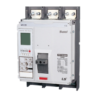
MCCB
2) Please consult us for the use of ZSI (Zone selective Interlocking).
RS - 485 communication
3) Refer to the catalogue for the connection of Trip relay and ZCT input terminals (E1,E2).
Auxiliary switch , Alarm switch
Long time delay trip indicator
AX , AL
LTD
Symbol and DESCRIPTIONS
4) UVT and SHT can not work together at the same time.
SHT
AX 1
AXc
AXb AXa
AX 2
AXc
AXb AXa
AX 3
AL
AL
ALb ALa
ALc
This diagram is based on "Opening" of circuit breaker,
de-energized and normal condition of Trip relay.
Internal/External wiring(by customer)
Connector of the control
circuit terminal of drawout type
Terminal code description
Voltage trip Device (SHT)
Under Voltage Trip (UVT)
 Loading...