17
Bit10 P3
Bit11 P4
Bit12 P5
Bit13 P6
Bit14 P7
Bit15 Not Used
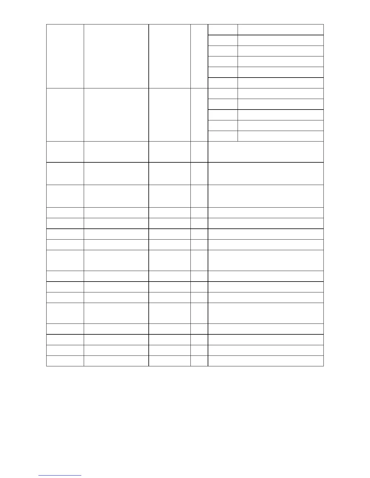
Bit00 30A – 30C
Bit01 1A – 1B
Bit02 2A – 2B
Bit03 OC1 - EG
0x0011
Output Terminal
Information
- R
Bit04~15 Not Used
0x0012 Analog Input 1 - R
Analog Input 1 (main manual Ai1)
-100.0%(FC17h).~.100.0%(03E8h)
0x0013 Analog Input 2 - R
Analog Input 2 (main manual Ai2)
-100.0%(FC17h) ~ 100.0%(03E8h)
0x0014 Analog Input 3 - R
Analog Input 3 (main manual Ai3)
-100.0%(FC17h) ~ 100.0%(03E8h)
0x0015 RPM - R Reverse speed: 1’s complement
note12)
0x0017 Speed Command Hz R/W SV-iV5 : used in Device Net
note13)
0x001D Speed Command1 RPM R Target Speed Command
0x001E Speed Command2 RPM R Ramp Speed Command
note14)
0x001F
Speed Controller Input
Command
RPM R Speed Controller Reference Speed
note15)
0x0020 Motor Speed RPM R note12)
0x0021 Torque Reference 0.1% R Torque Reference
note16)
0x0022 Torque Feedback 0.1% R Torque Feedback
note17)
0x0023 No-Load Current 0.1% R
PAR_26 Flux-Curr’s %
(Read : 0x050A
note28)
during operation)
0x0024 PID Reference 0.1% R PID Reference
note18)
0x0025 PID Feedback 0.1% R PID Feedback
note19)
0x0026 PID Output 0.1% R PID Output
note20)
0x0027 Inverter Temperature deg R Inverter Temperature
note6) Because other series (iS5, iG5, etc.) use addresses 0x0007 and 0x0008 for the Acceleration &
Deceleration Time in Device Net, same addresses are used for iV5. Besides Device Net,
Acceleration & Deceleration Time of addresses 0x0503 and 0x0504 may be used for SV-iV5.
note7) Hz is used for the motor speed feedback, only when communicating via Device Net.
note8) Indicates that the inverter is at a state of operating without trip. Indicates ‘1’ before, during, after
operation, when there is no trip.
note9) Indicates
‘
0
’when at stop
(bit0=
‘
1
’
), ‘1
’
when at forward run (bit1=
‘
1
’
),
‘
0
’
at reverse run (bit2=
‘
1
’
)