22
761E EXT_30 Parity/Stop 0 (8None/1Stop)
0 (8None/1Stop)
1 (8None/2Stop)
2 (8Even/1Stop)
3 (8 Odd/1Stop)
761F EXT_31 Delay Time 5ms
1000m
s
2ms
EX_01 [ Opt B/D]
z
A kind of the option board which is installed.
z
It is displayed automatically when the option board is installed.
EX_02 [ Opt Version]
z
A version of the communication option board.
EX_10 [ Output Num ]
z
Set the number of addresses at the read only area of the communication data.
z
Set addresses from EXT_11 to EXT_18 and the values can be 1~8.
EX_19 [ Input Num ]
z
Set the number of addresses at the write only area of the communication data.
z
Set addresses from EXT_20 to EXT_27 and the values can be 1~8.
EX_30 [ Parity/Stop ]
z
Set a Parity/Stop bit about communication.
EX_31 [ Delay Time ]
z
It carries on the communication smoothly by selecting an appropriate delay time.
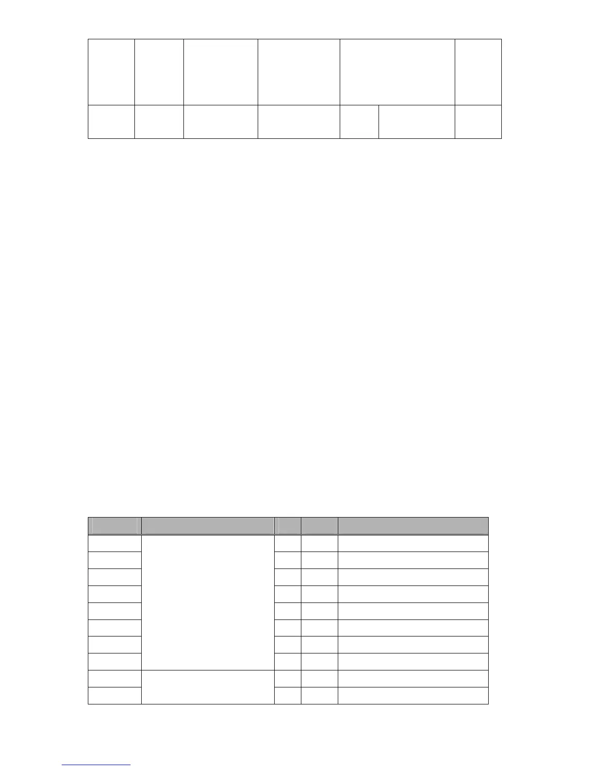
7.2.4 SV-iV5 Communication Area : SV-iV5’s Communication Data Area
Address Description Unit R/W Data Value
0x0100 - R Select address from EXT_11
0x0101 - R Select address from EXT_12
0x0102 - R Select address from EXT_13
0x0103 - R Select address from EXT_14
0x0104 - R Select address from EXT_15
0x0105 - R Select address from EXT_16
0x0106 - R Select address from EXT_17
0x0107
Select to-be-used address
from EXT_10[Output Num]
Save data sent from inverter
to communication card
Read only area
- R Select address from EXT_18
0x0108 - W Select address from EXT_20
0x0109
Select number of address
from EXT_19[Input Num]
- W Select address from EXT_21
 Loading...