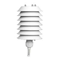
➢ Using DYA230 natural ventilation anti-radiant shield:
1. Fix the DYA049 supporting collar to the pole at a height of about
1.5 - 2 m.
2. Fix the DYA230 anti-radiant shield to the DYA049 supporting
collar.
➢ UsingDYA233 natural ventilation anti-radiant shield:
1. Fix the DYA046 bar on the pole.
2. Fix the DYA233 anti-radiant shield to the DYA046 bar.
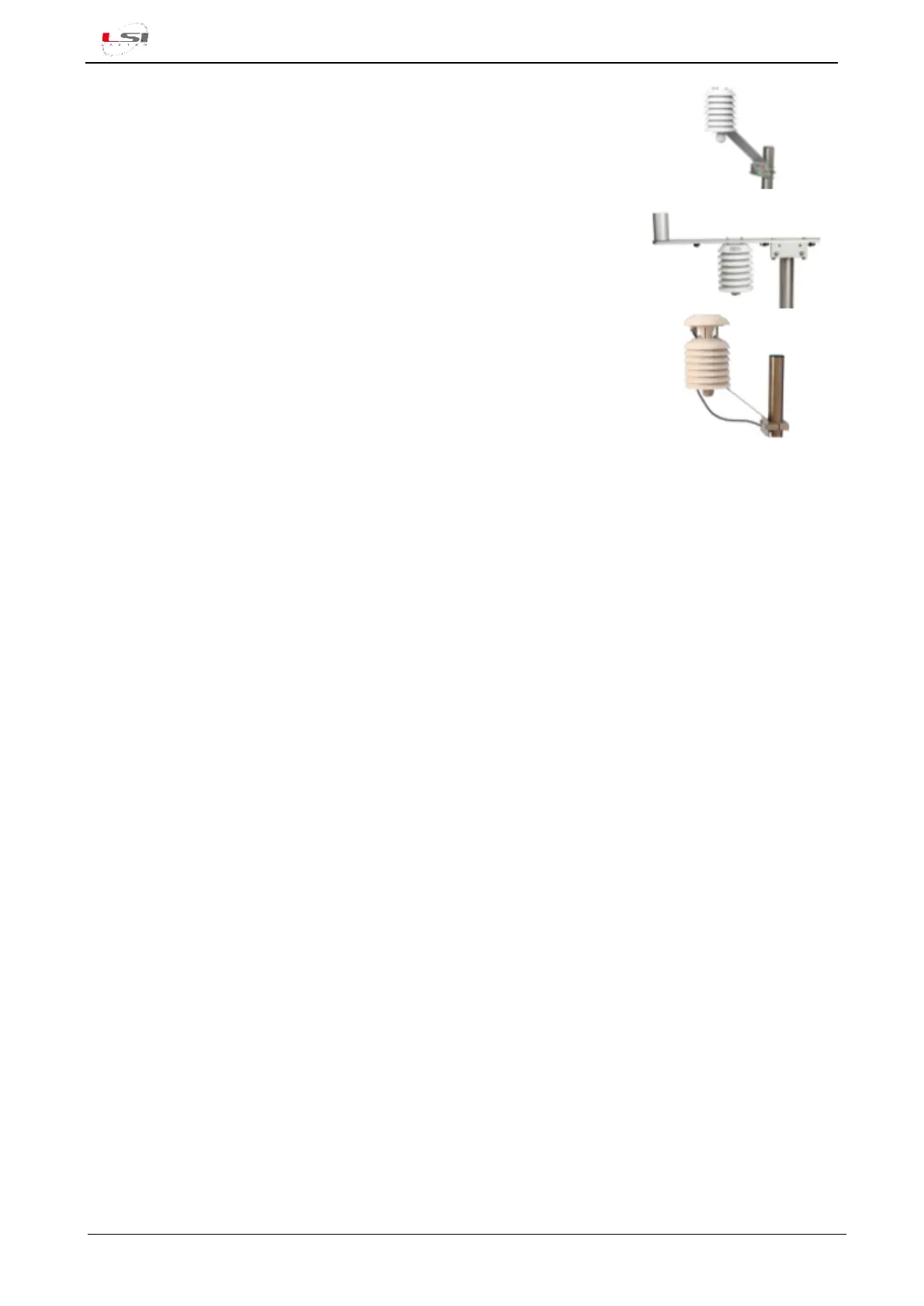
➢ Using DYA231 forced ventilatione anti-radiant shield:
1. Fix the DYA049 supporting collar to the pole at a height of about
1.5 - 2 m.
2. Fix the DYA231 anti-radiant shield to the DYA049 supporting collar
3. Insert the sensor stem inside the anti-radiant shield. The sensitive elements should result in the
central position on the anti-radiant shield and then secure it using the cable gland.
4. Run the cable to the data logger.
5. Connect the cable to the data logger as specified in the drawing (DISACC) supplied with the sensor.
3.2.2 DMA867, DMA875 and DMA975 sensors
1. Remove the cover from the sensor box and set the dip-switches for:
- 0…20 mA or 4…20 mA output
- Temperature measurement range
- Relative Humidity or Dew Point output
2. Fix the cover to the box.
3. Fix the DYA049 supporting collar to the pole at a height of about 1.5 - 2 m.
4. Fix the anti-radiant shield support to the DYA049 supporting collar.
5. Screw the DWA5xx cable connector onto the sensor box.
6. Connect the cable to the data logger as specified in the drawing (DISACC) supplied with the sensor.
3.2.3 EXP815 sensor
1. Fix the DYA049 supporting collar to the pole at a height of about 1.5 - 2 m.
2. Fix the anti-radiant shield support to the DYA049 supporting collar.
3. Remove the cover from the sensor box and move the ignition switch to ON; screw the cover to the
box.
4. Place/install the EXP301 receiver near the PC or data logger.
 Loading...