Starting Battery
Charger/Maintainer
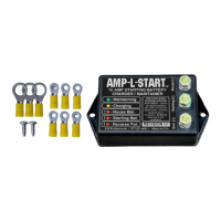
GENERAL INFORMATION — AMP-L-START™ is designed to keep your engine starting battery(s) fully charged during long periods of storage or inactivity. Connected
between the house and starting batteries, it diverts up to 15 amps of charging current from your existing house battery charger, sending it to the starting battery(s)
instead. This current automatically tapers to a small fraction of an amp after the starting battery(s) reaches a full state of charge. A set of indicator lights display the
charger's status and warns of improper hookup; an overvoltage protection feature automatically disconnects the starting battery(s) when excessive house battery voltage
is present; and an audible beeper warns of dangerously low starting battery voltage. The Revision F2 version also includes a user-selectable "High Temperature" mode
that reduces the turn-on and turn-off voltages to 12.7 and 12.5 volts, respectively, for computability with some temperature-compensated house battery chargers. This
mode is enabled by installing a jumper across two pins on the back of the unit. Removing the jumper instantly restores the original 13.2/12.8 volt turn-on/turn-off settings.
Step-By-Step Installation Instructions
USE CARE AROUND BATTERIES — SPARKS CAN IGNITE
HYDROGEN GAS. SHORT CIRCUITS CAN CAUSE BURNS OR FIRE.
CORROSIVE ACID CAN CAUSE SKIN BURNS OR BLINDNESS.
USE CARE IN DRILLING HOLES NOT TO CONTACT ANY
ELECTRICAL WIRING — HAZARD OF SHOCK, FIRE, BURNS.
STEP 1: After choosing one of the connection
methods described above, identify a flat mounting
surface for the AMP-L-START™, preferably near
your chosen wire connection points. Check that
drilling holes won't interfere with any wiring, hoses
or other parts on the other side. Next, temporarily
hold the AMP-L-START™ unit against your
intended mounting surface, and mark the hole
locations for the two mounting screws. Drill 1/8"
(3MM) holes at these location, and use two of the
sheet metal screws (included) to mount the unit.
STEP 2: Unplug from shore power, disconnect any
solar panels, and remove the negative terminals of
BOTH the house and starting battery banks. Next,
cut sufficient lengths of stranded automotive-grade
wire to connect the AMP-L-START™ to your
batteries or Isolator/Relay studs (as described
above). Use 12 gauge or thicker wire for HOUSE
[+] and STARTING [+] connections under 5 feet of
length (or 10 gauge for longer runs), and 18 gauge
or thicker wire for the GND. [–] connection.
Reconnect the negative terminals on your house and engine starting batteries (confirming that the red REVERSE POLARITY indicator is
not lit), reconnect any solar panels, and restore shore power. (Unit beeps and lights rapidly flash 4 times to confirm power-up). Finally,
peel the backing off the Status Indicator LEDs Description label, and affix it to a clean, flat surface near the AMP-L-START™ unit. This
completes the installation process.
These connections can either be made directly to the battery posts...
...or to terminals on your battery isolator or emergency start relay:
12 VOLT
STARTING
BATTERY(s)
BATTERY ISOLATOR
or EMERGENCY
START RELAY
To
Ignition or
Emergency
Start Switch
Connecting AMP-L-START™ directly to the battery posts is often simpler, since the batteries are usually easier to find than the Isolator or Emergency Start Relay.
However, connecting to the Isolator or Emergency Start Relay often results in much shorter wire runs, and avoids exposing the connections to corrosive battery fumes.
12 VOLT
STARTING
BATTERY(s)
(NOTE: In dual starting battery applications, the connections can be made to either starting battery.)
(NOTE: For tips on how to locate your Isolator or Relay, see the "Where's The Isolator?" section on Page 2.)
Strip approx. 1/4" of insulation off both ends of these 3 wires, select the
best size ring terminals (from the included assortment) to fit the AMP-L-
START™ and battery posts or Isolator/Relay , and crimp these terminals on
the bare wire ends. (NOTE: Use 3 of the smallest-diameter yellow ring
terminals for the studs on the AMP-L-START™.)
Crimp Here After
Inserting Wire
STEP 3: Use brass nuts and bronze split-ring lockwashers (included) to connect the 3 wires with ring terminals to the studs on the AMP-
L-START™ unit. CAUTION: Tighten the brass nuts only enough to compress the split-ring lockwashers - DO NOT
OVERTIGHTEN! Next, connect the opposite ends of these 3 wires with ring terminals to your chosen attachment points on the battery
posts or Isolator/Relay studs.
Installing AMP-L-START™ requires just 3 connections:
HOUSE [+] : This stud is connected to the positive terminal on your house battery(s). Use stranded automotive-grade
wire, 12 gauge or thicker (10 gauge if the wire length exceeds 5 feet).
STARTING [+] : This stud is connected to the positive terminal on your engine starting battery(s). Use stranded
automotive-grade wire, 12 gauge or thicker (10 gauge if the wire length exceeds 5 feet).
GND [–] : This stud is connected to chassis ground, which can also be the negative terminal on your house or starting
battery(s). Since this connection carries almost no current,18 gauge or thicker stranded automotive-grade wire will suffice.
(NOTE: The kit includes spares for easily-lost hardware.)