6
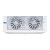
RIGGING AND MOUNTING
The unit can now be lifted to it’s final mounting position by inserting the
lifting forks into the pallet (Figures 4 & 5 - Step 8) and raising the unit
into place (Figures 4 & 5 - Step 9). On longer units it is important to find
the center “balance point” of the unit and spread the lifting forks wide
enough to avoid tipping.
UNIT MOUNTING POINTS
F31HC
F35HC
16.4
16.4
F31HC
F35HC
16.3
19.2
0.39
0.59
14.8
3/4”MPT
1.33
1.73
5.28 5.28
F31HC
F35HC
18.7
19.1
Fig. 1
Fig. 2
(0.39
375 (14.8)
F31HC
375 (14.8)
0.39
F35HC
14.8
14.8
2
1
Fig. 3
7
Fig. 4
Fig. 5
9
9
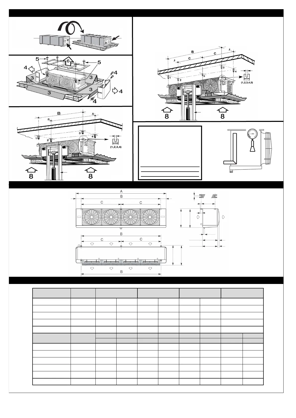
DIMENSIONAL DATA
Check coil pressure with an
accurate service gauge. If
pressure is “low” or “0” the
unit must be checked for
leaks before installation.
(Figure 3 - Step 7).
Do not return the unit to the
distributor or manufacturer
without prior authorization!
UNIT MOUNTING POINTS
Fig. 2
Unit Model Series
F31HC 115-4 116-4 125-4 126-4 135-4 136-4 146-4
F31HC 215-6 216-6 225-6 226-6 235-6 236-6 246-6
Number of Fans 12.4” Diam 1 1 2 2 3 3 4
Refrig Conn Liquid ½” ½” ½” ½” ½” ⅝” ⅝”
Refrig Conn Suction ⅝” ¾” ¾” ⅞” ⅞” 1-⅜” 1-⅜”
Dimension A 30 30 47-5/8" 47-5/8" 65-3/8" 65-3/8" 83-1/16"
Dimension B 19-3/8" 19-3/8" 37-1/8" 37-1/8" 54-13/16" 54-13/16" 72-1/2"
Unit Model Series
F35HC
73-4 106-4 145-4 215-4 272-4 323-4 362-4 430-4
F35HC
59-6 84-6 117-6 174-6 218-6 261-6 290-6 348-6
Number of Fans 13.8” Diam 1 1 2 2 3 3 4 4
Refrig Conn Liquid ½” ½” ½” ⅝” ⅝” ⅝” ⅝” ⅞”
Refrig Conn Suction 1-⅛” 1-⅛” 1-⅛” 1-⅛” 1-⅜” 1-⅜” 1-⅝” 1-⅝”
Dimension A 34" 34" 56" 56" 77-3/4" 77-3/4" 99-5/8" 99-5/8"
Dimension B 23-1/2" 23-1/2" 45-3/8" 45-3/8" 67-3/16" 67-3/16" 89-1/16" 89-1/16"
Dimension C --- --- --- --- --- --- 44-1/2" 44-1/2"
 Loading...