3
INSTALLATION / INSTALLATION / INSTALACIÓN
Modello
Modèle
Modelo
Type
Modell
F31HC...UL
F31HC...UL
F31HC...UL
115-4
215-6
315-7
116-4
216-6
316-7
125-4
225-6
325-7
126-4
226-6
326-7
135-4
235-6
335-7
136-4
236-6
336-7
146-4
246-6
346-7
Elettroventil.
Ventilatoren
Fans
Elèctroventil.
Ventilateurs
Ø 315 mm
(12.4 in)
n° 1 1 2 2 3 3 4
Attacchi Connection Raccords
Entrata inlet entrèe
Eintritt entrada
12 │½” 12 │ ½” 12 │ ½” 12 │ ½” 12 │ ½” 16 │ ⅝” 16 │ ⅝”
Anschlusse Conexiòn
Uscita outlet sortie
Austritt salida
16 │ ⅝” 18 │ ¾” 18 │ ¾” 22 │ ⅞” 22 │ ⅞” 35 │1 ⅜” 35 │1 ⅜”
Dimensioni Dimensions Dimensions
A
Abmessungen Dimensiones
B
Modello
Modèle
Modelo
Type
Modell
F35HC...UL
F35HC...UL
F35HC...UL
73-4
59-6
47-7
106-4
84-6
69-7
145-4
117-6
94-7
215-4
174-6
143-7
272-4
218-6
179-7
323-4
261-6
213-7
362-4
290-6
238-7
430-4
348-6
284-7
Elettroventil.
Ventilatoren
Fans
Elèctroventil.
Ventilateurs
Ø350 mm
(13.8 in)
n° 1 1 2 2 3 3 4 4
Attacchi Connection Raccords
Entrata inlet entrèe
Eintritt entrada
12 │ ½” 12 │ ½” 12 │ ½” 16 │ ⅝” 16 │ ⅝” 16 │ ⅝” 16 │ ⅝” 22 │ ⅞”
Anschlusse Conexiòn
Uscita outlet sortie
Austritt salida
28 │1 ⅛” 28 │1 ⅛” 28 │1 ⅛” 28 │1 ⅛” 35 │1 ⅜” 35 │1 ⅜” 42 │1 ⅝” 42 │1 ⅝”
Dimensioni Dimensions Dimensions
A
Abmessungen Dimensiones B
C
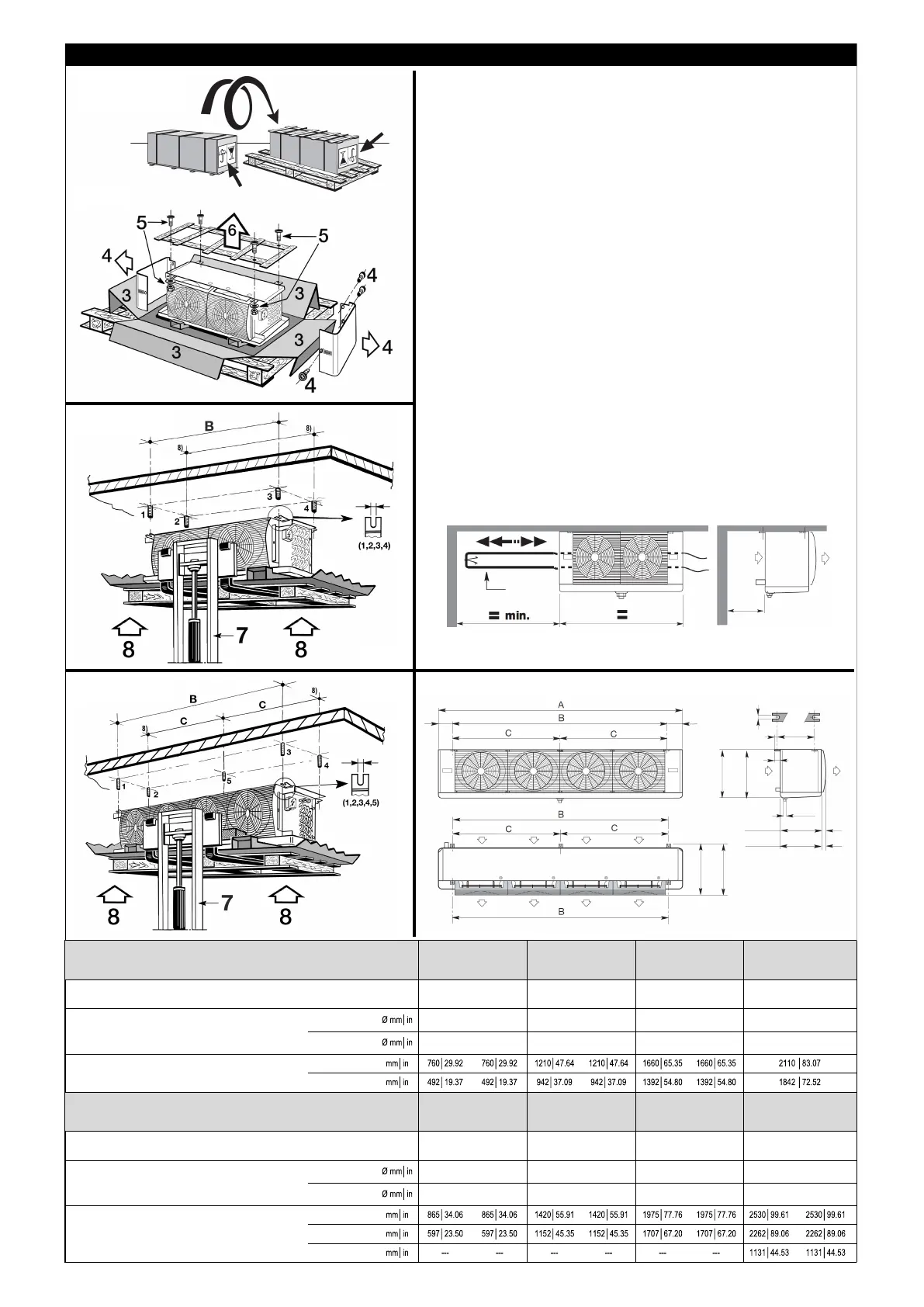
• Before lifting the units, please check the structural integrity of the
lifting devices
and their proper fixing to the structure (Fig. 2). It’s important that the
unit cooler is installed so as to leave space to the left of cooler (i.e.
facing fans)
for heater removal. It is also essential that the cooler is installed
level, to avoid drainage problems (Fig.3).
• Avant de soulever les appareils, contrôler que les dispositifs de
levage sont en
bon état et qu'ils sont fixés correctement à la structure (Fig. 2).
It est important de noter que l’appareil devra toujours être installé
avec un espace latéral libre égal à sa longueur; ceci pour permettre
l’eventuel remplacement des résistances électriques de dégivrage
(Fig.3).
• Antes de proceder en la elevación del aparato, se debe controlar
la integridad
estructural de la elevación y su posterior fijación correcta en la
estructura (Fig. 2).
El equipo debe colocarse de forma que deje un espacio lateral libre
equivalente al de su longitud total.
Ello permitirá la eventual sostitución de la resistencias eléctricas
(Fig. 3)
F31HC...UL - F35HC...UL
F31HC...UL
F35HC...UL
416 (16.4)
416 (16.4)
F31HC...UL
F35HC...UL
415 (16.3)
487 (19.2)
10 (0.39)
15 (0.59)
375 (14.8)
3/4 GAS
34 (1.33)
44 (1.73)
134 (5.28) 134 (5.28)
F31HC...UL
F35HC...UL
476 (18.7)
486 (19.1)
Fig.3
HEATERS
RESISTANCE
RESISTANCIA
500 mm
(19.7 in)
F31HC...UL
F35HC...UL
Fig.1
10 (0.39)
375 (14.8)
F31HC...UL
Fig.2
375 (14.8)
10 (0.39)
F35HC...UL Fig.2
375 (14.8)
375 (14.8)
 Loading...