14
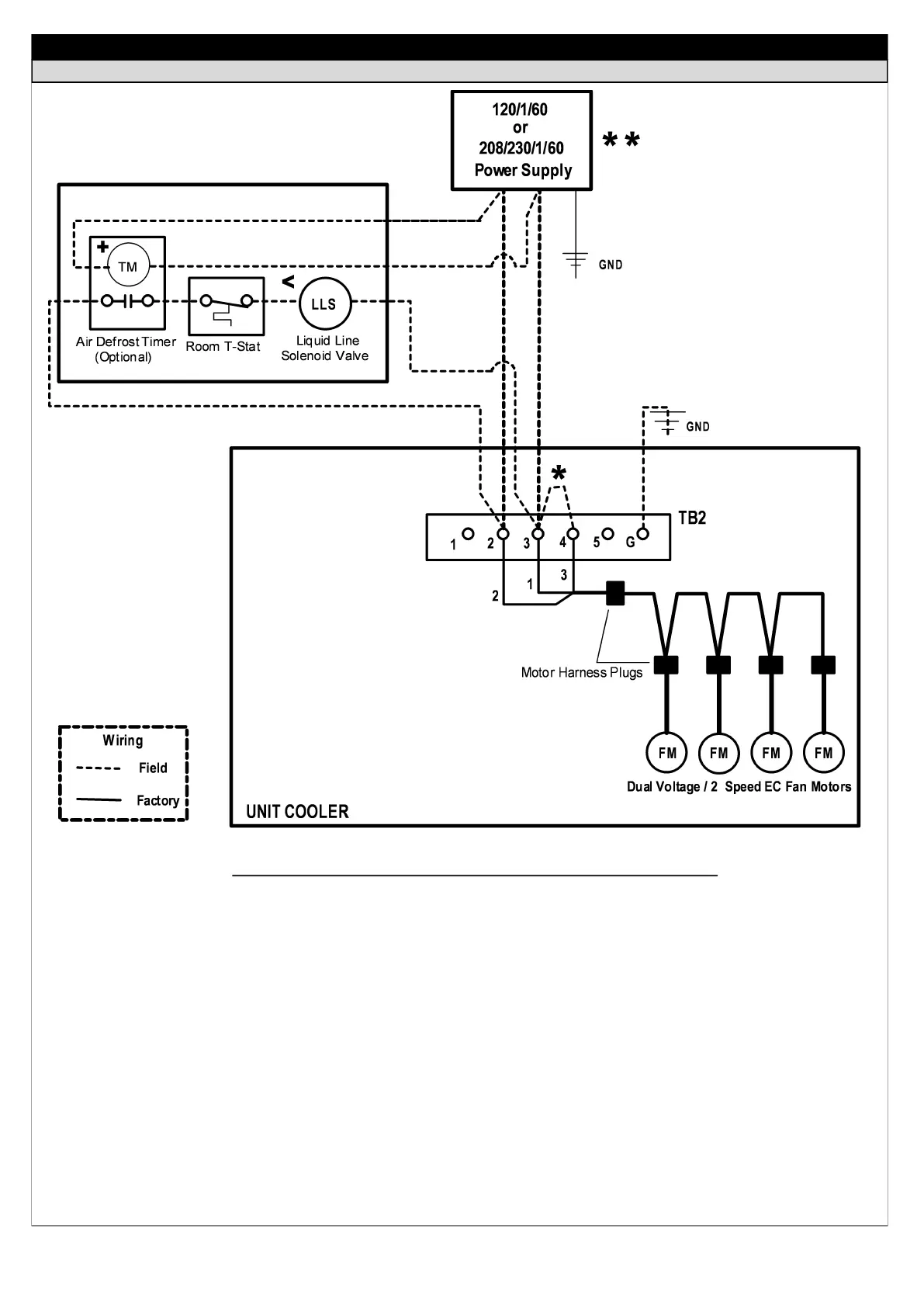
AIR DEFROST — 115/1/60 OR 208/230/1/60 UNIT COOLER
FIELD WIRING DIAGRAMS — TYPICAL
IMPORTANT WIRING NOTES - INSTALLER PLEASE READ CAREFULLY!
Sub-circuit fusing or service disconnect switches are not shown but may be required as per the NEC and / or local codes.
It is the responsibility of the installing contractor to interpret and comply with all applicable electrical codes.
Field install an 18 GA jumper wire between terminals 3 & 4 on terminal block TB2 for continuous low speed fan operation (950
RPM). Fan motors will operate continuously on high speed without jumper wire installed (F31 Models Units - 1300 RPM / F35
model units - 1450 RPM). See page 21 for optional two speed fan relay control wiring if required.
An air defrost time clock may be supplied as an option (either field installed or factory mounted on the system condensing unit).
The room thermostat and liquid line solenoid valve are shown as field installed but may be factory mounted in the unit cooler.
Make sure the solenoid holding coil is wired for the correct control voltage (115 or 230).
*
+
<
**
 Loading...