20
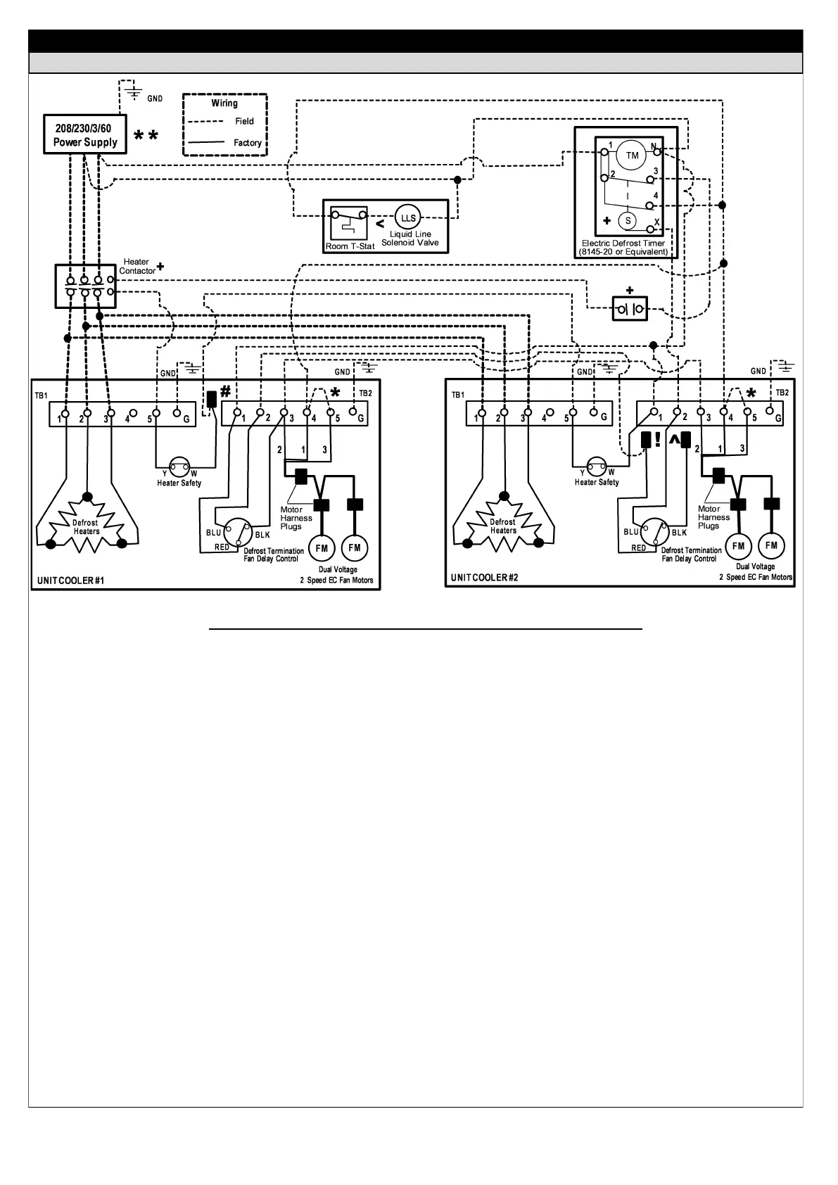
FIELD WIRING DIAGRAMS — TYPICAL
ELECTRIC DEFROST — 208/230/3/60 — (2) UNIT COOLERS / (1) HEATER CONTACTOR
IMPORTANT WIRING NOTES - INSTALLER PLEASE READ CAREFULLY!
Sub-circuit fusing or service disconnect switches are not shown but may be required as per the NEC and / or local codes. It is
the responsibility of the installing contractor to interpret and comply with all applicable electrical codes.
Field install an 18 GA jumper wire between terminals 3 & 4 on terminal block TB2 for continuous low speed fan operation (950
RPM). Fan motors will operate continuously on high speed without jumper wire installed (F31 Models Units - 1300 RPM / F35
model units - 1450 RPM). See page 21 for optional two speed fan relay control wiring if required.
The defrost time clock, block out relay / auxiliary switch and heater contactor are all typically located in the system condensing
unit. All unit cooler power should feed from this unit. Make sure the total heater amp draw per unit cooler does not exceed the
resistive amp rating of the contactor. Also be sure the wire gauge size is adequate to carry the total amp load required.
When connecting (2) electric defrost unit coolers to (1) defrost timer remove the black wire from the defrost termination / fan
delay control which is factory wired to terminal 2 - TB2 on unit cooler #2 and cap the wire. This will allow the fan delay on unit
cooler #1 to control the fans on both unit coolers.
When connecting (2) electric defrost unit coolers to (1) defrost timer remove the red wire from the defrost termination / fan
delay control which is factory wired to terminal 4 - TB1 on unit cooler #2 and hard wire to a field wire connected to terminal 1 -
TB2 on unit cooler #1. This will place the (2) defrost termination controls in series so that both units must reach temperature in
order to terminate the defrost cycle.
The room thermostat and liquid line solenoid valve are shown as field installed but may be factory mounted in the unit cooler.
Make sure the solenoid holding coil is wired for the correct control voltage (115 or 230).
**
*
+
<
^
!
 Loading...