22
FIELD WIRING DIAGRAMS — OPTIONSs
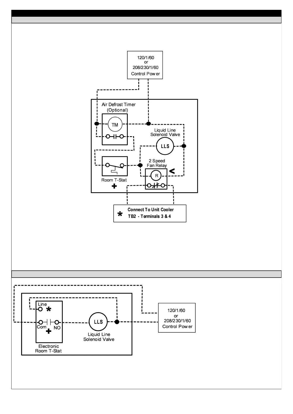
TWO SPEED FAN MOTOR RELAY WIRING OPTION
Installing this relay will allow the unit cooler fans to operate at low speed whenever the room thermostat is satisfied or the
unit is in defrost (when optional, off-cycle “air” defrost timer is used), resulting in reduced operating costs over the life of the
equipment.
Remove jumper wire (if installed) between unit cooler terminals 3 & 4 before connecting relay wires.
Be sure that fan relay coil voltage matches unit cooler control voltage. Wire across normally open (NO) relay contacts.
Single Pole — Single Throw Thermostat
+
<
*
ELECTRONIC ROOM THERMOSTAT WIRING OPTION
Be sure that room thermostat
power wiring matches the unit
cooler control voltage.
Wire across normally open
(NO) thermostat contacts.
+
*
 Loading...