7
RECOMMENDED UNIT COOLER PLACEMENT
Air flow within the refrigerated space is critical to achieving optimum cooling and freezing results. If air flow is compromised
for any reason the unit may not provide satisfactory cooling performance. There are many potential reasons for poor air
flow - few of which are the result of inadequate system capacity or unit malfunction. Some of the more obvious reasons for
poor airflow include;
- Unit installed above doors (coil blocked with frost / ice)
- Insufficient return air space between unit and wall
- Insufficient free area in front of the unit
- Unit mounted to close to beams or product racking
- Multiple units installed to close together
- Low ceiling height / unit mounted to close to floor level
- Units mounted perpendicular / blowing at right angles to each other
- Poor product packaging or improper product stacking arrangement
- Too much product loaded into the room at one time
- Wrong unit design for application
- Too few units for room volume
- Multiple, miss-matched units or fan types used in the same room
For the best possible cooling performance always consider the following design recommendations;
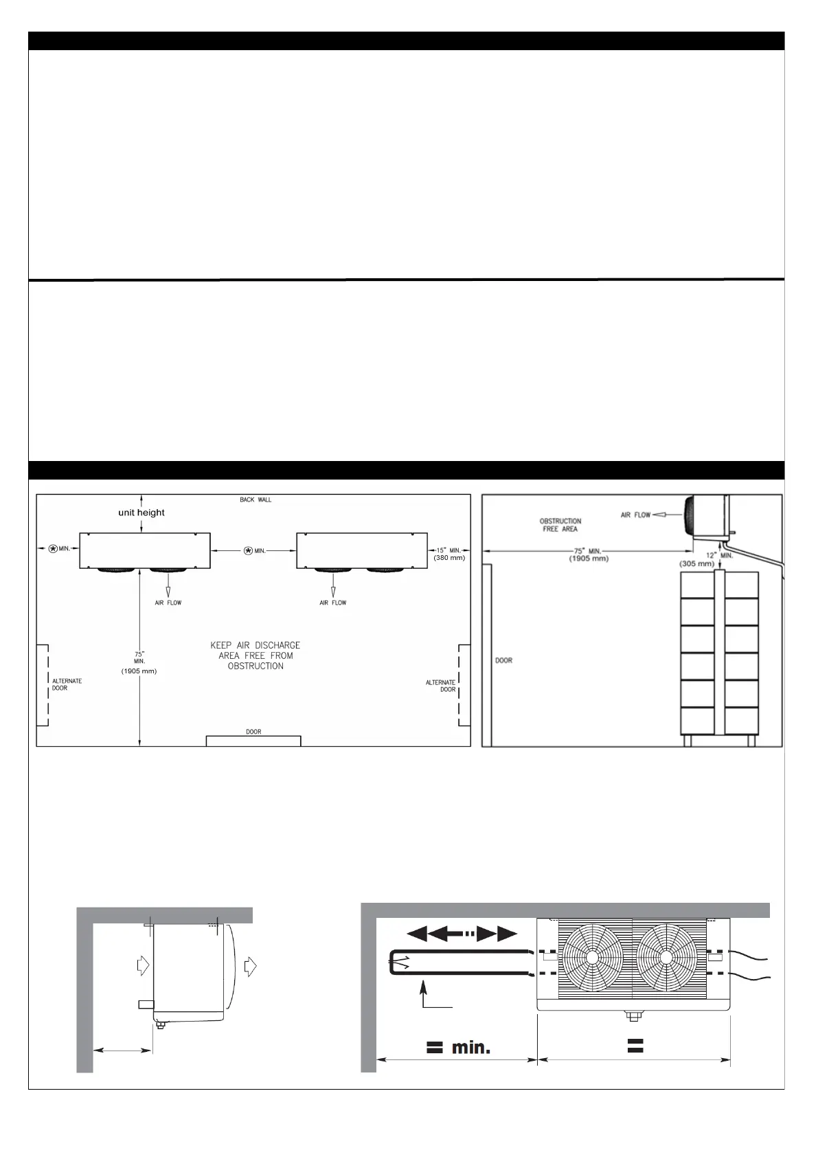
• Always locate units as far away from door openings as possible - preferably blowing directly towards doors or other openings.
• Allow a minimum return air space behind the coil equal to the height of the unit (Figure 10 - below).
• On larger installations place units where they can blow freely down open aisleways between product racking / shelves.
• Mount units directly to the ceiling whenever possible (greater overall air throw is partially achieved by increasing the distance
between the unit and the floor).
• For blast chilling or freezing applications consideration must be given for installing air baffles, discharge chutes, coves, return
air plenums, etc. to prevent air bypass / recirculation due to high external static pressure.
TYPICAL UNIT COOLER PLACEMENT IN COOLER / FREEZER
Minimum clearance required for coil heater replacement is the length of the unit (electric defrost models). Heaters are remove-
able from the refrigerant connection end of the unit.
In addition to the above consideration should also be given to the potential length and layout of refrigerant piping runs and condensate
drain lines based upon the unit coolers’ physical location. It is always preferable to minimize the length of these runs - particularly in-
side the conditioned space. Minimum clearances must also be maintained around the unit to allow access for service, routine mainte-
nance and cleaning of the unit when required. For electric defrost units the minimum service access required to replace the coil de-
frost heaters is illustrated below (Figure 11- below).
19.2”
Fig. 10
HEATER
Fig. 11
*
 Loading...