EasyManua.ls Logo

LUBRIQUIP Trabon Series User Manual

LUBRIQUIP Trabon Series
4 pages
To Next Page IconTo Next Page
Page #1 background imageLoading...
Page #1 background image
© LUBRIQUIP, INC., 1963. Revised May 1996. All Rights Reserved.
DESCRIPTION
In a Trabon Series-Flo System
®
, free flow of lubricant from the
pump through the transmission system and the bearings is
necessary. If any portion of this transmission system (a divider
valve, line fitting or any bearing) does not freely accept and
pass its portion of the lubricant a blockage has occurred. This
blockage will cause a higher than normal pumping pressure to
be developed by the pump. Depending on the application or
system design, this blockage with its resultant high pump
pressure will usually cause a complete loss of lubricant flow
into the total system and no bearing will be receiving lubricant.
The loss of flow due to a blockage is first indicated with the
higher than normal system pressure that is developed by the
pump as it attempts to overcome this blockage. This abnor-
mally higher pressure that is a result of a blockage is limited,
isolated, and signalled through the use of various performance
indicators, reset and relief, incorporated into the system
design.
Divider Valve —
A Series-Flo
®
type divider valve is a manifolded proportioning
device consisting of an inlet and end section plus a minimum of
three intermediate sections. The divider valve is manifolded
together with tie rods and nuts. A master divider valve is the
first divider valve downstream from the lube pump. A second-
ary divider valve is any divider valve receiving lubricant from
the master divider valve.
Intermediate Sections —
Intermediate sections (three or more required per manifold)
contain a piston specially fitted to that section, built in outlet
check valves and various passageways that, working with the
piston, meters and valves the flow of lubricant. See Figure B.
Intermediate sections may be manufactured to require one (1)
or two (2) lube outlets. Stamping located on the face of each
section will indicate (1) the style of divider valve section (MSP,
MX, etc.), (2) the discharge per piston stroke expressed in
thousandths of cubic inches (35 = .035 in
3
) and (3) the number
of lube outlets required (S = single, one outlet only; T = twin,
two lube outlets required). See Figure A.
Warning —
Never block a lube outlet that is designed to discharge
lubricant.
Figure A. Components of the MSP Divider Valve
Figure B. Intermediate Valve & Subplate Section
Locating Blockage in Series-Flo
®
Systems
Bulletin 30101
Operation and Service Instructions
LUBRIQUIP
BY
®
and
Question and Answer IconNeed help?

Do you have a question about the LUBRIQUIP Trabon Series and is the answer not in the manual?

LUBRIQUIP Trabon Series Specifications

General IconGeneral
BrandLUBRIQUIP
ModelTrabon Series
CategoryLubrication systems
LanguageEnglish

Summary

Description of Series-Flo Systems

Divider Valve Functionality

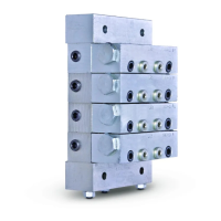
A manifolded proportioning device with inlet, end, and intermediate sections for lubricant distribution.

Intermediate Section Details

Sections with pistons that meter lubricant flow, featuring stamped specifications for output.

Performance Indicators for Lubrication Systems

Reset Indicator with Memory

Stops lube system operation on fault, signaling blockage location manually.

Rupture Indicator Function

Used on high-pressure MSH valves, ruptures a disc to indicate blockage.

Automatic Relief Indicator Operation

Pinpoints blockages but allows continued lubrication to other points.

Rupture-to-Atmosphere Indicator

Provides pump protection by venting lubricant on excessive pressure.

Troubleshooting Blockages in Series-Flo Systems

Initial System Inspection

Visually inspect system for crushed lines, improper installations, or blocked outlets.

Testing Master Divider Valve

Use manual pump to pressure test master divider valve with or without indicators.

Testing Secondary Divider Valves

Isolate blockages by testing downstream secondary divider valves and their outlets.

Divider Valve Disassembly and Cleaning

Disassemble and clean divider valves when testing indicates an internal blockage.

Maintenance and Contamination Control

Cleaning Divider Valve Components

Clean sections and pistons thoroughly in solvent, dry with compressed air, and inspect for damage.

Assembly Torque Specifications

Follow specified torque values for tie rod nuts, indicator plugs, and end plugs during reassembly.

Addressing Contamination Blockages

Eliminate contamination sources by inspecting filtration and reservoir filling methods.

Resolving Separation Blockages

Consult lubricant supplier for grease separation issues causing thickener deposition.