EasyManua.ls Logo

LUCCI Air 210667 - User Manual

LUCCI Air 210667
9 pages
Print Icon
To Next Page IconTo Next Page
Loading...
Installation Instructions
1 | P a g e v 1.1 ( 09/ 2 0 20)
TOUCH REMOTE CONTROL FOR CEILING FAN
SKU# 210667
Rated Voltage 220V - 240V~ 50Hz
Thank you for purchasing this quality Lucci product. To ensure correct function and safety, please read and follow all
instructions carefully before assembly, installation and use of this product. Please keep the instructions for future reference.
Warranty
This product is covered by a 12-month warranty. The warranty is from date of purchase, not the date of installation.
If this product is not assembled and installed by a licensed electrician, the warranty will be void.
Please retain proof of purchase and evidence of installation by a licensed electrician for any warranty enquiries.
Warranty will be void if there is any damage due to improper usage or modification to the product.
Failure to comply with the instructions in this manual may increase the risk of damage or injury and will void warranty.
Installation Requirements
The receiver must be installed by a licensed electrician.
All wiring and installation of this product must adhere to latest local and national wiring rules.
eg. AS/NZS 3000 Electrical installations in Australia.
NOTE: A double pole wall switch must be included in the wiring installation. The double pole switch allows
the receiver to disconnect from the mains 240VAC power during maintenance and cleaning of the ceiling fan.
NOTE: Do not install the receiver with an existing fan wall controller. Remove any existing fan wall controller
and replace with a double pole wall switch, to power the receiver.
Do not exceed rated power input specification.
Select a suitable location for installation:
This product is suitable for indoor use only.
The receiver must be installed in the canopy of the ceiling fan.
NOTE: This ceiling fan remote controller is only suitable for controlling the ceiling fan motor and the light kit
associated with the ceiling fan only. Any other use would be considered as misuse and warranty will be void.
NOTE: The controller wiring circuit must NOT be shared with any electrical equipment that is sensitive to
voltage fluctuation, such as infrared sensor lights.
DO NOT use the wiring of the controller, other than for the purpose of supplying power into the controller and
connections to the equipment that is under control. Any outside wiring connections which are not part of the
controller/controlled circuit, may affect the operation of the controller and will void warranty.
This remote control is only suitable where the receiver can be inserted inside the canopy cover safely and securely.
The maximum ceiling pitch angle should not be exceeded. It will damage the receiver and result in electric shock.
Please check with the retailer about the maximum pitch angle suitable for ceiling fan with remote control.
Do not use a solid state dimmer with this ceiling fan receiver.
Fan installation must be complete including assembly of blades before operating the remote control.
Take care not to pull any electrical wires during unpacking as this may damage the connection.
Lay out all the components on a smooth surface and make sure there are no components missing before assembling.
If parts are missing, return the complete product to the place of purchase for inspection or replacement.
Question and Answer IconNeed help?

Do you have a question about the LUCCI Air 210667 and is the answer not in the manual?

Summary

Warranty Information

Warranty Coverage

Provides a 12-month warranty from purchase date; void if improperly installed or modified.

Installation Requirements

Electrician Requirement

Receiver installation must be performed by a licensed electrician.

Wiring Compliance

All wiring must adhere to local and national wiring rules, e.g., AS/NZS 3000.

Wall Switch Mandate

A double pole wall switch is required for safe power disconnection during maintenance.

Receiver Placement and Fit

Install receiver inside the ceiling fan canopy, ensuring secure fit and correct pitch angle.

Operational Restrictions

Use only for intended fan/light control; avoid sensitive equipment and unauthorized wiring.

Component Compatibility

Do not use with existing fan wall controllers or solid state dimmers.

Type 1 Fan Installation Guide

Pre-installation Steps

Switch off power, uninstall canopy, and disconnect existing wiring.

Receiver Wiring Connections

Connect receiver input to bracket and output to fan body connector.

Final Assembly Steps

Position receiver securely and reinstall canopy.

Type 2 Fan Installation Guide

Pre-installation Steps

Switch off power, uninstall canopy, and disconnect existing wiring.

Adaptor Loom Connection

Connect receiver output to adaptor loom and loom to fan body connector.

Earthing Wire Connection

Connect earthing wire to bracket point, ensuring full continuity.

Receiver Placement

Insert receiver into mounting bracket spacing, avoiding wire damage.

Final Assembly Steps

Install canopy back onto the bracket.

Remote Holder Mounting

Holder Installation

Locate a suitable wall and fix the remote control holder using screws.

Remote Insertion

Slide the remote control into the mounted holder.

Remote Battery Setup

Initial Battery Film Removal

For first-time use, remove the battery film from the remote control.

Battery Replacement Procedure

Loosen screw to remove cover, access battery compartment, and install correctly.

Securing Battery Cover

Re-attach and secure the battery compartment cover by re-tightening the screw.

Single Fan Pairing Procedure

Pairing Steps

Turn off/on power, install battery, press specific buttons on remote to pair with receiver.

Pairing Confirmation

Turn on fan and adjust speed via remote to confirm successful pairing.

Pairing Troubleshooting Tips

Repeat pairing steps if the initial attempt is unsuccessful.

Multiple Fan Pairing Guide

Individual Fan Pairing Process

Pair each fan/receiver individually by isolating power to other fans.

Resetting to Default

Press and hold specific buttons for 10 seconds to reset the remote to all receivers.

Remote Control Button Guide

Understanding Button Functions

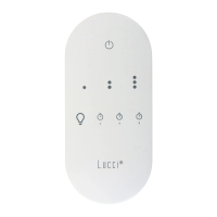
Details fan speed, light control, and timer setting buttons.

Receiver LED Indicator

The red LED on the receiver flashes when remote buttons are activated.

Remote Memory Function

Remote memorizes last status when turned off via the wall switch.

Battery Safety Precautions

Child Safety and Ingestion

Keep batteries away from children; seek immediate medical help if ingested.

Disposal and Leak Handling

Dispose of batteries safely, handle leaks cautiously, and contact poison control if needed.

General Safety and Specifications

Safe Product Usage

Ensure power OFF for maintenance, use only with fan, supervise children, avoid liquids.

Technical Product Data

Details product SKU, voltage, load, weight, dimensions, frequency, and battery type.

Overview

This document provides installation instructions and operational guidelines for the Lucci air Touch Remote Control for Ceiling Fan, SKU# 210667. This remote control system is designed to manage ceiling fan speed and light functions.

Function Description:

The Lucci air Touch Remote Control system consists of a receiver and a remote transmitter. The receiver is installed within the ceiling fan's canopy and connects to the fan's motor and light kit. The remote transmitter allows users to wirelessly control the fan's speed (low, medium, high), turn the fan ON/OFF, turn the light ON/OFF, and set a timer for 2, 4, or 8 hours. The system is specifically designed for use with AC motor ceiling fans and non-dimmable LED lights. It features a memory function that recalls the last fan and light status when power is restored.

Important Technical Specifications:

  • SKU #: 210667
  • Rated Voltage: 220-240V~50Hz
  • Rated Load:
    • Motor: Max. 0.75A (for AC motor ceiling fans only)
    • Light: Max. 100W, 100VA LED (Non-dimmable)
  • Weight: 0.2kg / Set
  • Dimensions:
    • Receiver: H:28mm W:80mm L:125mm
    • Transmitter: H:15mm W:55mm L:120mm
  • RF Frequency: 433.92MHz
  • Range: 10m
  • Battery: DC 3V CR2450 button battery (included as accessory)
  • Warranty: 12-month warranty from the date of purchase. Warranty is void if not installed by a licensed electrician, if there is damage due to improper usage or modification, or if instructions are not followed.

Usage Features:

  • Remote Control Buttons:
    • LED Indicator: A red LED on the receiver flashes when buttons are active.
    • Fan Speed Control: Dedicated buttons for low, medium, and high speeds.
    • Fan ON/OFF: A button to turn the fan OFF.
    • Light ON/OFF: A button to toggle the light ON/OFF.
    • Timer Settings: Buttons for 2, 4, and 8-hour timer settings.
  • Memory Function: The remote has a memory function that will memorise and recover the last status of the fan or light when turned on next, even if turned off by a wall switch.
  • Vibration Feedback: The remote will vibrate when buttons are active, in addition to the LED indicator flashing.
  • Pairing Remote & Receiver:
    • Single Fan Installation: After installation, the remote and receiver must be paired. This involves turning OFF the mains supply, installing the battery in the remote, turning ON power to the receiver, and within 60 seconds, pressing and holding the light button and 8-hour timer button simultaneously for 5 seconds.
    • Multiple Fan Installation (2 or more fans in one location): To prevent interference, each fan's remote/receiver can be set to a different code. This requires individual isolation switches for each fan. The pairing process involves isolating power to all but one fan, then pairing that fan's receiver with the remote, and repeating for subsequent fans.
    • Reset to Default: The remote can be reset to be compatible with all receivers by pressing the light button and 8-hour timer button simultaneously for 10 seconds, during which the indication light will flash rapidly.
  • Remote Control Holder: A holder is provided for wall mounting the remote control using two screws.

Maintenance Features:

  • Battery Replacement: The remote control requires one 3V CR2450 battery. For first-time use, a battery film must be removed. To replace the battery, a screw on the battery compartment cover needs to be loosened. The screw does not fully detach from the cover. Ensure correct battery polarity during installation.
  • Cleaning: Always ensure power is OFF before performing any cleaning. Do not soak or immerse the product in water or other liquids. Avoid contact with corrosive chemicals/solvents or abrasive cleaners.
  • Troubleshooting: If pairing is unsuccessful, repeat the pairing steps.
  • Safety Precautions for Battery:
    • Keep new and used batteries away from children.
    • Do not ingest the battery due to chemical burn hazard.
    • Always use the specified 3V CR2450 DC battery.
    • Ensure correct battery polarity.
    • Disconnect the ceiling fan from mains supply during battery insertion/replacement to prevent false operation.
    • Remove batteries if the product is not used for long periods.
    • Remove batteries from the remote transmitter before discarding it.
    • Regularly check the battery compartment cover for secure closure. Stop using if cracked or damaged.
    • Dispose of used batteries safely; contact local council for disposal information.
    • Batteries should only be installed or replaced by an adult.
    • If a coin/button cell battery is swallowed, seek immediate medical attention (call Poisons Information Centre on 13 11 26).
    • Handle leaked battery chemicals with caution; avoid contact with eyes or ingestion.

Installation Requirements:

  • Installation must be performed by a licensed electrician.
  • All wiring and installation must adhere to the latest local and national wiring rules (e.g., AS/NZS 3000 Electrical installations in Australia).
  • A double pole wall switch must be included in the wiring installation to disconnect the receiver from mains power during maintenance.
  • Do not install the receiver with an existing fan wall controller; replace any existing controller with a double pole wall switch.
  • Do not exceed rated power input specifications.
  • The product is suitable for indoor use only.
  • The receiver must be installed inside the canopy of the ceiling fan.
  • This remote controller is only for controlling the ceiling fan motor and its associated light kit. Misuse will void the warranty.
  • The controller wiring circuit must not be shared with electrical equipment sensitive to voltage fluctuation (e.g., infrared sensor lights).
  • Only use the controller's wiring for supplying power to the controller and connections to the controlled equipment. Any other outside wiring will void the warranty.
  • The remote control is only suitable if the receiver can be safely and securely inserted into the canopy cover.
  • Do not exceed the maximum ceiling pitch angle; check with the retailer for suitable angles.
  • Do not use a solid-state dimmer with this receiver.
  • Fan installation, including blade assembly, must be complete before operating the remote control.
  • Take care not to pull electrical wires during unpacking.
  • Lay out all components and ensure none are missing before assembly. If parts are missing, return the product to the place of purchase.

Installation Procedures:

The manual outlines two types of ceiling fan installations based on the earth wire configuration:

  • Type 1 (Earth wire separate from quick connector): The additional adaptor loom is NOT required. Instructions detail connecting the bracket's quick connector to the receiver input, and the receiver output to the ceiling fan body connector.
  • Type 2 (Earth wire incorporated with quick connector): The additional adaptor loom (Fig. 3) IS required. Instructions detail connecting the bracket's quick connector to the receiver input, the receiver output to the male end of the adaptor loom, the female end of the adaptor loom to the ceiling fan body connector, and the adaptor loom's earthing wire to the bracket's earthing point. An earthing continuity test is recommended.

In both types, the receiver is carefully inserted above the hanger ball in the mounting bracket, ensuring no wiring is damaged or loosened, before reinstalling the canopy.

LUCCI Air 210667 Specifications

General IconGeneral
BrandLUCCI Air
Model210667
CategoryRemote Control
LanguageEnglish