363-205-401 Power Up: DLP-519
Issue 7, March 1997 Page 3 of 4
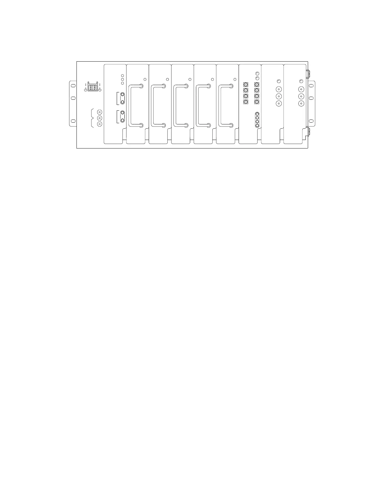
Figure 2 – J1C182BD Power Shelf
4. Condition DMM to measure DC volts.
5. Connect DMM test leads to
- (1A/mV)
and
+ (VOLTAGE)
on the power shelf
(bottom 2 jacks).
6. Does DMM indicate between −54 and −55 volts?
If
YES,
then proceed to Step
12.
If
NO,
then continue with Step
7.
7. Condition DMM to measure AC volts.
8. Operate AC power circuit breaker off and then back on.
9. Verify AC power is connected to
P112
on the side of the power shelf. Check
for presence of 105 to 129 volts AC at TB1 rear of power shelf (pin3 neutral;
pin1 θ1 RECTs 1, 2, 3; pin4 θ2 RECTs 4 and 5).
10. Is correct voltage present?
If
YES,
then proceed to Step
11.
If
NO,
then
refer trouble to installation group.
11. Check wiring on power shelf using SD-7C163-01. Repeat procedure from Step
4
after trouble is found and corrected.
CB2
CB1
ALARM
RECTIFIER
336 A1 PU
ALARM
RECTIFIER
336 A1 PU
CURRENT
(1A/mV)
-
BAT
+
1
(1A/mV)
BOD
BAT +
NORMAL
AUG4
FAIL
CURRENT
+
RECTIFIER
RECT2
BATTERY
CURRENT
-
BATTERY
+
2
INTERFACE
UNIT
VOLTAGE
FUSES: 30A
125 V
RECT1BIU
-
ALARM
RECTIFIER
336 A1 PU
+20HZA
+20HZB
-48V
GND
RMN
+20HZ
0.5A
AUG3
RMJ
RING CONTROL
UNIT
RCURECT5
336 A1 PU
ALARM
RECTIFIER
336 A1 PU
ALARM
RECT4RECT3
1
-20HZ
0.5A
2
3
4
GND
-20HZ
FAIL
-48V
3H1
RINGING
GENERATOR
RG
RING GEN1
GND
-20HZ
FAIL
-48V
3H1
RINGING
GENERATOR
RG
RING GEN2
Lucent Lucent Lucent Lucent Lucent Lucent Lucent Lucent Lucent
Lucent
 Loading...