Power Up: DLP-524 363-205-401
Page 8 of 8 Issue 7, March 1997
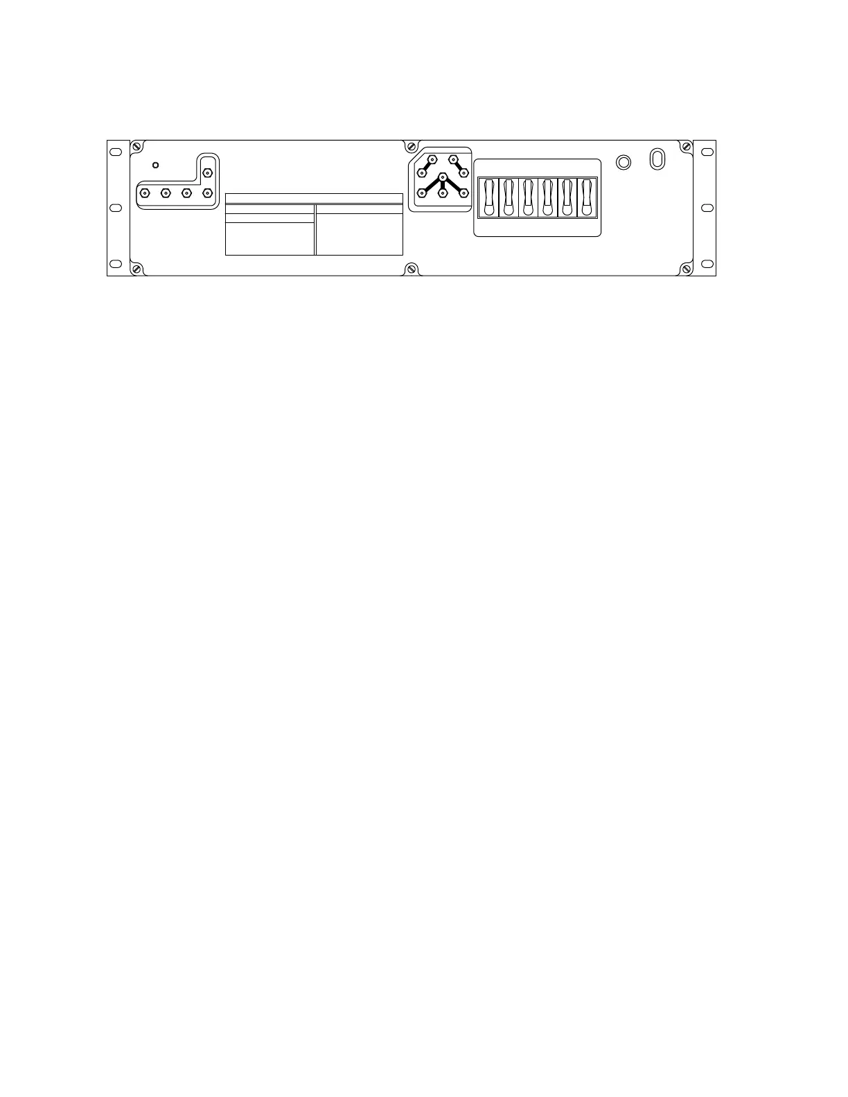
Figure 4 – Control & Distribution Panel
29. Does meter indicate battery string voltage of 49.5 V DC or higher?
If
YES,
then proceed to Step
30.
If
NO,
then continue with Step
29.
30. Visually inspect cable assembly between control & distribution panel and bat-
tery string. Replace cable assembly fuse and/or cable assembly until meter
indicates correct voltage.
31. Is this the last battery string to be installed?
If
YES,
then proceed to Step
31.
If
NO,
then repeat from Step
1
for next battery string.
32. Reconnect any battery strings disconnected for battery string voltage mea-
surement. Close and secure doors to battery compartment.
STOP. YOU HAVE COMPLETED THIS PROCEDURE.
ed-83114-30
CB6CB5CB4CB3CB2CB1
normal
disconnect
low volt
discharge
bat on
TEST
OPEN BAT
BAT2BAT1 BAT3
BATC
BAT4
BATTERY CURRENT:
OPEN BATTERY TEST
Control & distribution
rectifier 3 * rc3 - RR
battery 4 * bat4 - batc
battery 3 * bat3 - batc
battery 2 * bat2 - batc
Battery 1 * bat1 - batc
TO MEASURE * USE TEST POINTS
rectifier 2 * rc2 - rr
rectifier 1 * rc1 - rr
rectifier current:
plant current * pc - pcr
plant voltage * pv - pvr
To measure * use test points
POWER PLANT TEST POINTS
RC1 RC2
PVR
RR
PV
RC3
PC
PCR
 Loading...