363-205-401 Power Up: DLP-534
Issue 7, March 1997 Page 3 of 6
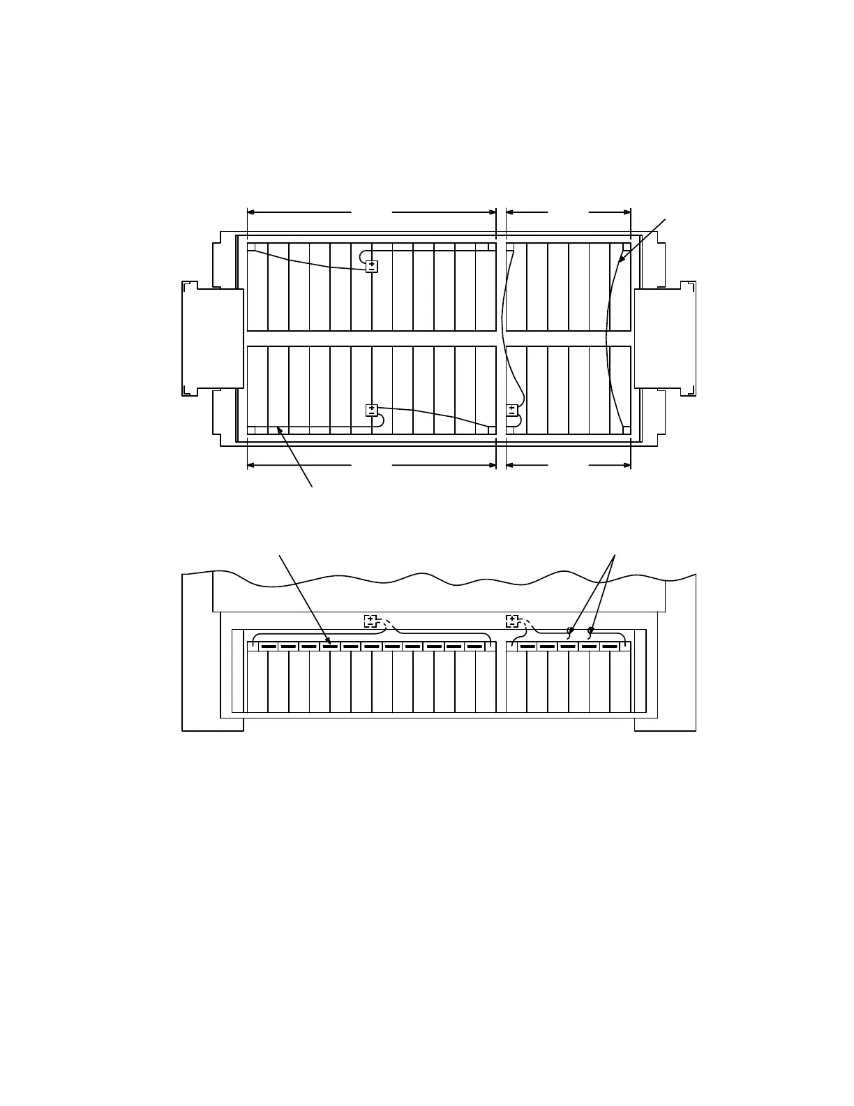
9. Place all twelve batteries in the battery compartment as shown in Figure 1.
Figure 1 – Layout of Lineage 2000 VR Series Batteries in 80D Cabinet
10. Coat inter-battery bus bars with NO-OXid grease and install on the batteries as
shown in Figure 2. Install 1/4 inch lock washer and nut on battery post. Using
insulated torque wrench with the socket, tighten nut to 55 in-lbs torque. Repeat
for each battery post until all 12 batteries are connected together.
Comment: For battery string 3 the 12 batteries are connected in 2
groups of 6 batteries. A cable connects
+
of battery 6 to
-
of
battery 7 using the hardware to connect the inter-battery bus
bar.
Cable
Patch
Top View
Side 2
6
7
12
12
12
- + - +
6
String #2 String #3
891091011 111212345678
Interbattery Bus Bar To Side 2
345
- +- +- +- +- +- +
Side 1
678
- +- +
9
- + - +- +- +- +
34521
- +
11 12
- +
Front View
- +
10
Battery String Cable
String #1
345
34 1256789101112
String #3
 Loading...