363-205-401 Power Up: DLP-535
Issue 7, March 1997 Page 5 of 8
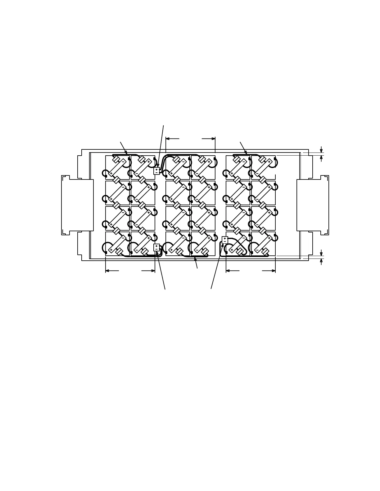
16. As shown in Figure 2, place the left 4 batteries (batteries
1
through
4
with
cable assemblies) in battery compartment in position for battery string 1.
Ensure the first and fourth batteries are 1 inch away from the battery compart-
ment doors.
Figure 2 – RT Battery Strings and Connections
String # 1
Patch Cord
Main Connector
54
Side 2
String #1
Main Connector
Side 1
String 1
63
72
1 8
8
5
6
7
String #2
1
String 2
4
3
2
Leave approximately 1 in. (2.5 cm)
of space per side between batteries
and battery cover panel to avoid
interference when closing.
String #3
Note:
Main Connector
(2.5 cm)
1 in.
String # 1
Patch Cord
54
(2.5 cm)
1 in.
63
7
8
String 3
2
1
String # 2
Patch Cord
 Loading...