363-205-401 RT Turn Up:
Issue 7, March 1997 Page 1 of 2
DLP-504
Install Channel Fuse Unit (CFU)
1. Get
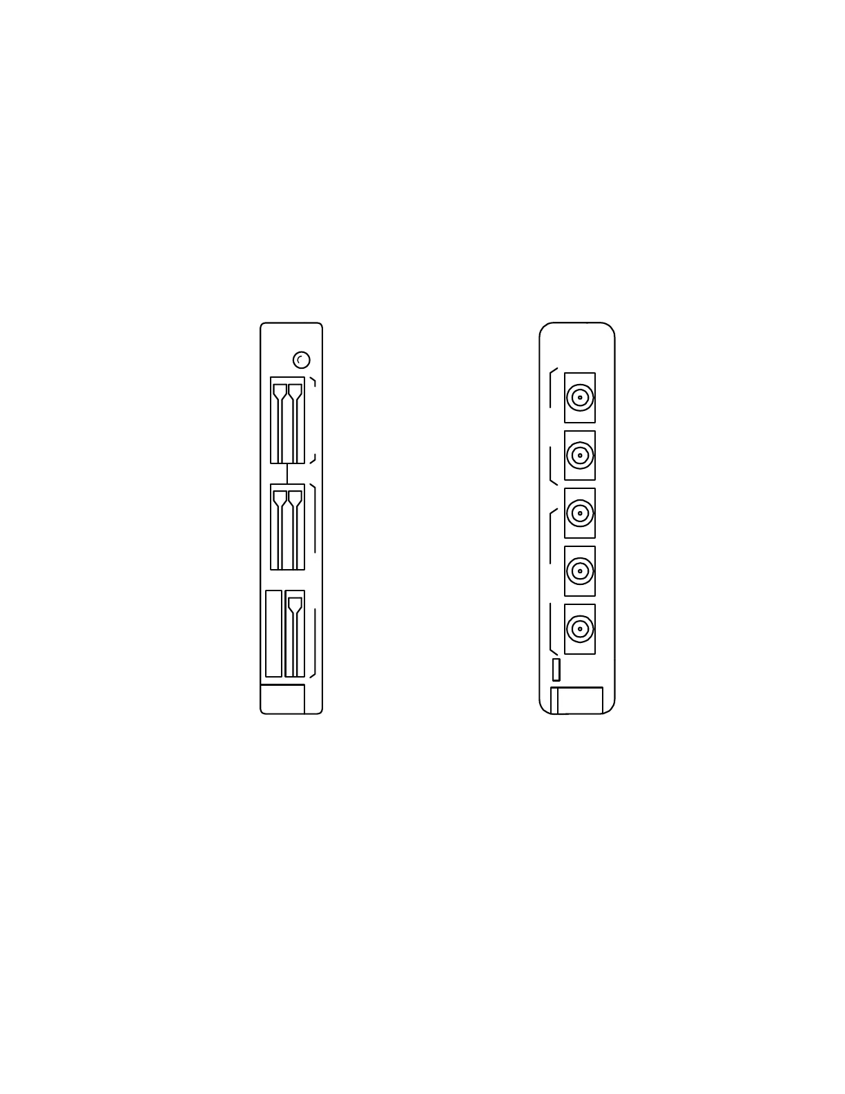
AUA114
or
39E CFU
(Figure 1) and inspect for possible damage.
Figure 1 – AUA114 and 39E Channel Fuse Unit
2. Verify per Table A or Table B that fuse holders on faceplate of
CFU
contain
correct value fuses and that fuses are not blown (fuse is blown when flag pro-
trudes on faceplate). If a fuse is blown, use appropriate extractor tool (see
Step 7) to replace fuse.
3. Install
CFU
into vacant
CFU
slot in upper or lower bank.
–48V 3A
AUA114
CFU
CMN
–20Hz 0.5A
ALM
CDAB
–48V
39E
CFU
CDABCDAB
20HZ
CMN