Do you have a question about the Lumedica OQ LABSCOPE 3.0 and is the answer not in the manual?
Explains the basics of Optical Coherence Tomography.
Details about the company's mission and founding.
Provides contact information for assistance and inquiries.
Explains OCT imaging principles, resolution, and applications.
Discusses benefits and drawbacks of OCT technology.
Outlines essential safety precautions for operating the system.
Lists prohibited uses and actions to avoid to prevent misuse.
Specifies that only trained personnel should service the system.
Provides guidelines for handling, packing, and cleaning the system.
Lists potential risks associated with equipment use and movement.
Instructs on proper disposal procedures for the system.
Lists items included in the standard OQ LabScope package.
Lists items included in the optional workstation package.
Step-by-step guide for assembling the scanner stand.
Instructions for connecting and setting up the OQ LabScope system.
Details connecting the monitor, keyboard, and mouse.
Explains how to log into Windows and launch the OQ LabScope software.
Guides through performing the first scan and adjusting focus.
Overview of the main software interface and its primary functions.
Instructions on how to start and stop an OCT scan.
Differentiates between alignment and capture scan modes.
Describes how to save B-scan images from the software.
Defines key terms like A-scan, B-scan, Scan Width, and offsets.
Defines A-scan as primary data collected by OCT systems.
Defines B-scan as the OCT image showing sample depth.
Explains the scan width setting for B-scan length.
Defines horizontal offset for MEMS mirror positioning.
Defines vertical offset for MEMS mirror positioning.
Explains the term 'lines' in context of scan patterns.
Describes Horizontal, Vertical, Cross, and Circle alignment scan types.
Details the horizontal scan pattern moving left to right.
Details the vertical scan pattern moving front to back.
Combines horizontal and vertical scans for a comprehensive view.
Describes the circle-shaped scan pattern around the sample.
Details Radial, Circle, Long, Multi Line, and Volume capture scan types.
Configures lines and width for the radial scan pattern.
Configures circles and width for the circle scan pattern.
Configures B-scans and A-scans per B-scan for dense scans.
Configures lines and B-scans per line for multi-line scans.
Configures B-scans and width for volume scans.
Explains how to adjust scan parameters in the configuration tab.
Details how to save images from the scan buffer to storage.
Describes how to navigate between software functions using the panel.
Explains how to use the File menu, including exiting the software.
How to use the View menu to check image attributes.
Accessing software version and support contact via the Help menu.
Explains how the software creates folders and files for data.
Adjusts the liquid lens focus for the OCT scanning beam.
Sets the bottom value of the intensity range for image contrast.
Sets the second order coefficient for dispersion compensation.
Sets the third order coefficient for dispersion compensation.
Averages all scans currently in the scan buffer.
Saves a single B-Scan image displayed in the left panel.
Saves the average B-Scan image displayed in the right panel.
Saves all B-Scan images in the scan buffer to disk.
Saves raw B-Scan data from the spectrometer to files.
Controls image intensity range and buffer selection for single B-scans.
Controls image intensity range for average B-scans.
Selects which image from the buffer is displayed in the single B-scan view.
Tools for adding measurements like calipers to B-scan images.
Tools to add horizontal and vertical calipers for measurements.
Tool to measure the thickness of a single layer within a region of interest.
Detailed explanation of the layer thickness measurement tool and its output.
Controls scan types for aligning the sample with the OCT system.
Sets the horizontal position of the MEMS scan.
Sets the vertical position of the MEMS scan.
Sets the relative length of the B-Scan.
Determines A-scans, B-scans, and width for each scan pattern.
Configures lines and width for radial scans.
Configures B-scans and width for volume scans.
Configures circles and width for circle scans.
Configures B-scans and A-scans per B-scan for dense scans.
Configures lines and B-scans per line for multi-line scans.
Determines measurement options available in the Review tab.
Sets scaling for reporting vertical lengths based on refractive index.
Sets scaling for reporting horizontal widths.
Enables Caliper or Layer Thickness tools in the Review tab.
Procedure to calibrate depth measurements using a ruler and software settings.
Procedure to calibrate width measurements using a ruler and software settings.
Filters voxels based on brightness in 3D rendering.
Saves a PNG image of the current volume scan orientation.
Saves a DICOM file of the B-scans used to construct the volume scan.
Rotates volume rendering to view from a specific axis.
Displays translucent planes intersecting the volume for cross-section views.
Shows raw output from the spectrometer for system diagnosis.
Adjusts horizontal/vertical position of the MEMS mirror.
Sets the focus of the liquid lens for the scanning beam.
Adjusts the power output percentage of the Superluminescent Diodes.
Sets the path length of the reference arm.
Preset values for the reference arm used with different lenses.
Controls light reflected from the reference arm using a liquid lens.
Manual control of reference arm power level via liquid lens focus.
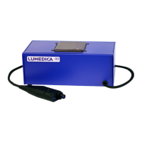
Describes the main housing unit of the OQ LabScope system.
Details the computer unit integrated within the system.
Information about the power cord and its connection requirements.
Notes about the permanent connection between system engine and scanner.
Provides dimensional drawings and specifications of the scanner.
Explains how polarization affects signal and checks for cord issues.
Lumedica's offering for end-of-life system returns in the EC.
Lists services not covered under the end-of-life return program.
Instructions for proper disposal if not returning the system to Lumedica.
Steps to try for quick resolution of software errors, including power cycling.
Contact information and required details for further assistance.
Explains the use of TeamViewer for remote technical support.
Details the standard warranty coverage period for OCT imaging systems.
Information on purchasing extended warranty coverage.
Describes charges for repairs not covered by the warranty.
Lists conditions and modifications that void the system warranty.
| Category | Medical Equipment |
|---|---|
| Light Source | Superluminescent Diode (SLD) |
| Center Wavelength | 840 nm |
| Bandwidth | 50 nm |
| A-scan Rate | 20 kHz |
| Axial Resolution | 5 µm |
| Lateral Resolution | 15 µm |
| Imaging Depth | 2.5 mm |
| Scan Area | 6 mm x 6 mm |
| Dimensions | 200 mm x 150 mm x 100 mm |
| Weight | 5 kg |
| Power Requirements | 100-240V AC, 50/60 Hz |
| Connectivity | USB 3.0 |
| Intended Use | Optical Coherence Tomography for ophthalmic imaging |
| Software | Included proprietary software |
| Working Distance | 20 mm |
| Illumination | LED |
| Power Supply | External Power Adapter |