EasyManuals Logo

Lumel RE72 User Manual & Quick Start

Lumel RE72
To Next Page IconTo Next Page
To Previous Page IconTo Previous Page
Page #26 background imageLoading...
Page #26 background image
pl EN



       
      

2
.
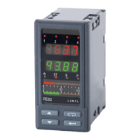
The controller has two separable terminal strips with screw terminals.
Strips enable to connect all signals by a wire of 2.5 mm
2
cross-section.
Fig. 3. View of controller connecting strips
Fig. 4. Supply
 supply



interface RS485




 output 4
 supply
zasilanie
wycie1
wecie
132
31
30
29
28
27
26
25
24
23
22
21
20
19
17
18
2
3
4
5
6
7
8
9
10
11
12
13
14
15
16
wecie dodatkowe
wecieprzekładnika
weciebinarne 1
weciebinarne 2
interfejsRS-485
wycie2
zasilanieprzetwornikó
w
wycie3
wycie4




 input
 output 3

transducer supply
 output 2
 output 1
17
18

Other manuals for Lumel RE72

Questions and Answers:

Question and Answer IconNeed help?

Do you have a question about the Lumel RE72 and is the answer not in the manual?

Lumel RE72 Specifications

General IconGeneral
BrandLumel
ModelRE72
CategoryController
LanguageEnglish