Do you have a question about the Lumitec Poco and is the answer not in the manual?
Specifies the required DC power source and explains how the POCO module replaces physical switches.
Details MFD/wireless device connectivity and guides on calculating amp draw for system planning.
Provides guidance on fuse sizing based on light count and highlights PLI compatibility importance.
Outlines connecting the POCO to chart plotters (MFD) and mobile devices via the Lumitec app.
Provides default SSID, access code, Wi-Fi password, and web interface for POCO connection.
Details assigning channels and clans for light locations to create custom light groups.
Explains creating simple switches or scene switches with custom intensity and color settings.
Guides on selecting locations and adding created switches to layout pages within the interface.
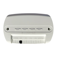
Explains the meaning of indicator lights for power, channels, and Wi-Fi/Bluetooth connection status.
The Lumitec Poco Digital Lighting Control system is a sophisticated solution for managing marine lighting, designed to integrate seamlessly with various boat systems. It replaces traditional physical switches with a digital interface, offering enhanced control and customization over your vessel's lighting.
The Poco system acts as a central hub for your boat's lighting, allowing you to control multiple light groups from a single interface. It communicates with lights via Power Line Instruction (PLI) technology, which uses existing power wires to transmit control signals, simplifying installation and reducing wiring complexity. The system supports a wide range of Lumitec PLI-compatible lights, including aft hardtop lights, aft spreader lights, forward hardtop lights, forward spreader lights, under gunwale lights, and underwater lights.
The core functionality revolves around creating and managing "light groups" and "switches." Light groups allow you to categorize and control sets of lights based on their location or function (e.g., "LG_aft_hardtop," "LG_underwater"). Switches, on the other hand, are the virtual controls you interact with to activate or adjust these light groups. These switches can be simple, controlling a single light group with a specific intensity and color, or they can be complex "scene switches" that activate multiple light groups simultaneously with predefined settings, creating custom lighting atmospheres for different activities like "Night Fishing."
The Poco system is designed for flexible control. It can be connected to a Multi-Function Display (MFD) on your boat, allowing you to manage lights directly from your chart plotter. Alternatively, it can be controlled via a dedicated mobile application available for Apple and Google Play devices, providing remote access and convenience. The system utilizes both Wi-Fi and Bluetooth-LE for connectivity, ensuring reliable communication with your control devices.
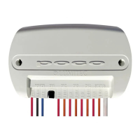
Installation begins by connecting the Poco module to your boat's 12 or 24 VDC battery. The module has dedicated input channels (CH1 IN to CH4 IN) for power from fuse/breaker panels, and corresponding output channels (CH1 OUT to CH4 OUT) to power your lights. Each input channel requires a fuse, with a maximum of 10A, to protect the system. The ACC IN and PWR IN terminals also require a 3A fuse. The system includes an Ethernet connection for optional integration with MFDs.
Once physically installed, the system requires configuration through its digital interface. This involves several key steps:
The system also features a "Calculate Your Amp Draw" section, which is crucial for proper system design. It provides examples of amp draw for different light configurations and emphasizes that the total amps per channel must remain below 10 Amps to prevent overloading. Amp draw information for specific lights is available on their product packaging or on the Lumitec website.
The Poco system includes status indicators to help monitor its operation and troubleshoot any issues:
These indicators provide immediate visual feedback on the system's status, allowing users to quickly identify if there are power issues, communication problems, or active dimming. For more detailed information and troubleshooting, users are directed to the Lumitec website. The system's reliance on PLI technology means that all installed lights must be PLI compatible. Users are advised to check for the PLI icon on product packaging and refer to the Lumitec website for additional installation information regarding non-PLI or non-Lumitec brand lights.
| Operating Voltage | 10-30V DC |
|---|---|
| Voltage Range | 10-30V DC |
| IP Rating | IP67 |
| Input Voltage | 12V DC |
| Voltage | 12V |