EasyManua.ls Logo

Lunos 5/ZII - User Manual

Lunos 5/ZII
2 pages
Print Icon
To Next Page IconTo Next Page
Loading...
Mounting Instructions for the
Micro Controller Time lag Type 5/ZII
Order No.: 039857 - Please pass on to User -
Application
The time lag module 5/ZII is a program-
mable control for fan motors:
Functions:
- Switch-on delay
- Time lag
- Inverse operation
- Interval switching
Coupling to room lighting is possible.
Inappropriate application is not admissi-
ble.
Technical Data:
Supply voltage 250VAC/50 Hz
Operating voltage range: 180 VAC to 275
VAC
Operating switching current: max. 0.5 A
Electr. power input: max. 115 W
Delay times: adjustable (refer to diagram
„Switch settings“)
Factory setting:
- Switch-on delay 120 sec.
- Time lag 15 min.
- Interval switching OFF
- Inverse operation OFF
The time lag module is EMC-tested and
EMC-compatible.
Dimensions:
35
49
10
brown
blue
white
black
Switch settings:
Interval ON every 4
hours for 30 min
*
Interval OFF
Time delay 15 min
Time delay 6 min
Inverse operation ON 30 min
Time lag after leaving the
room *
Inverse operation OFF
Switch-on delay
120 sec.
Switch-on delay
0 sec.
* depending on the time lag
set
Factory
setting:
white switch
knob
- Switch-on
delay 120 sec.
- Time lag
15 min.
-Inverse oper-
ation OFF
- Interval
switching OFF
Installation in junction box
36
Ø70
Installation in switch
60
Ø60
Installation
The time lag module can be appropri-
ately installed, as illustrated, in a stand-
ard junction box or a standard switch
box (60 mm deep).

Other manuals for Lunos 5/ZII

Question and Answer IconNeed help?

Do you have a question about the Lunos 5/ZII and is the answer not in the manual?

Summary

Application and Functions

Module Application

Describes the time lag module 5/ZII as a programmable control for fan motors.

Module Functions

Lists the core functions: switch-on delay, time lag, inverse operation, interval switching, and coupling to room lighting.

Technical Specifications and Setup

Technical Data

Details supply voltage, operating voltage range, switching current, and electrical power input.

Dimensions

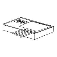
Provides physical dimensions of the time lag module.

Switch Settings

Illustrates how to adjust delay times and function settings using miniature switches.

Installation Guide

Installation Locations

Explains that the module fits standard junction or switch boxes (60 mm deep).

Installation in Junction Box

Diagram illustrating the module's installation within a standard junction box.

Installation in Switch Box

Diagram showing the module's installation within a standard switch box.

Safety and Operation

Safety Instructions

Crucial warnings for safe handling, including disconnecting power and using residual current protection.

Operating Unit Functions

Details on using Interval switching, Time lag, Inverse operation, and Switch-on delay.

Electrical Connections

General Connection

Diagram for LUNOS fans without a time lag module installed.

Time-Lag Controlled Ventilation

Wiring diagram for time-lag controlled ventilation on demand.

Continuous and Demand Ventilation

Diagram for basic ventilation with switchable time-lag controlled demand.

Lunos 5/ZII Specifications

General IconGeneral
BrandLunos
Model5/ZII
CategoryMicrocontrollers
LanguageEnglish