Technical Assistance
For questions concerning the installation or
operation of this product,
call the Lutron Technical Support Center.
Please provide exact model number when calling.
U.S.A. and Canaday (24 hrs / 7 days)
1.800.523.9466
Fax +1.610.282.6311
México +1.888.235.2910
Other Countries 8am – 8pm ET
+1.610.282.3800 www.lutron.com
Limited Warranty
(Valid only in U.S.A., Canada, Puerto Rico, and the Caribbean.)
Lutron will, at its option, repair or replace any unit that is defective in materials or manufacture within one year after purchase. For warranty
service, return unit to place of purchase or mail to Lutron at 7200 Suter Rd., Coopersburg, PA 18036-1299, postage pre-paid.
THIS WARRANTY IS IN LIEU OF ALL OTHER EXPRESS WARRANTIES, AND THE IMPLIED WARRANTY OF MERCHANTABILITY IS LIMITED
TO ONE YEAR FROM PURCHASE. THIS WARRANTY DOES NOT COVER THE COST OF INSTALLATION, REMOVAL OR REINSTALLATION,
OR DAMAGE RESULTING FROM MISUSE, ABUSE, OR DAMAGE FROM IMPROPER WIRING OR INSTALLATION. THIS WARRANTY DOES
NOT COVER INCIDENTAL OR CONSEQUENTIAL DAMAGES. LUTRON’S LIABILITY ON ANY CLAIM FOR DAMAGES ARISING OUT OF OR IN
CON NEC TION WITH THE MANUFACTURE, SALE, INSTALLATION, DELIVERY, OR USE OF THE UNIT SHALL NEVER EXCEED THE PUR CHASE
PRICE OF THE UNIT.
This warranty gives you specific legal rights, and you may have other rights which vary from state to state. Some states do not allow the
exclusion or limitation of incidental or consequential damages, or limitation on how long an implied warranty may last, so the above limitations
may not apply to you.
This product is covered under one or more of the following U.S. patents: 5,248,919; 5,399,940; 5,637,930; 5,798,581; 6,169,377; 6,380,696;
7,362,285; 7,365,282; 7,408,525; 7,548,216; 7,573,436 and corresponding foreign patents. U.S. and foreign patents pending. Lutron, Claro,
Maestro, Maestro Wireless, The Sunburst Logo and Satin Colors are registered trademarks and FASS is a trademark of Lutron Electronics Co.,
Inc. NEC is a registered trademark of National Fire Protection Association, Quincy, Massachusetts. © 2009 Lutron Electronics Co., Inc.
Lutron Technical Support Center 1.800.523.9566 24 hrs / 7 days
The Wireless Controller can also be mounted to the left or right of existing lighting controls,outlets or
other Wireless Controllers. For these configurations please visit www.lutron.com/maestrowireless.
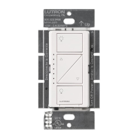
Using the Wireless Controller on a Wall
Off
LU TRON
Light
On
Adjust
Off
LU T R O N
Light
On
Adjust
Off
LU TRON
Light
On
Adjust
Off
LU TRON
Wall Mount
Backplate
Template: For Mounting Directly to a Wall or
in a 1-Gang Wallplate
For all other configurations please visit www.lutron.com/maestrowireless
Continued from front
6
7
Ground
Green wire
Black screw
Brass screw
Atenuador
Ground
Tag
Green wire
Black screw
Brass screw
Blue screw
Ground
Tag
Green wire
Black screw
Brass screw
Blue screw
Ground
Tags
Green wire
Black screw
Brass screw
Blue
screw
Dimmer or Companion Dimmer
Ground
Tag
Green wire
Black screw
Brass
screw
Blue screw
Dimmer or Companion Dimmer
Blue
Live
120 V~
60 Hz
Neurtral
Light
Fixture
Brass
Black
Green
Ground
Wallbox
Dimmer
Blue
Live
120 V~
60 Hz
Blue
Neutral
Light
Fixture
Brass
Brass
Black
Black
Green
Green
Ground
Ground
Wallbox
Dimmer or
Companion Dimmer
Dimmer or
Companion Dimmer
Wallbox
Two Location Wiring Diagram
Wiring the Dimmer:
Connect the • green ground wire on the Dimmer to the bare copper or green ground wire in the
wallbox. (See Important Note 2 on other side.)
Connect either of the wires removed from the switch to the • black screw terminal on the Dimmer.
Connect the remaining wire removed from the switch to the • brass screw terminal on the Dimmer.
Tighten the • blue screw terminal on the Dimmer. It is not used in a single-pole circuit.
Single Location Wiring Diagram
5b – Two-Location Control
One location will be replaced with a Dimmer and the other with a Companion Dimmer.
5c – Three or More-Location Control
One location will be replaced with a Dimmer and the others with Companion Dimmers. Only one Dimmer can
be used with up to nine Companion Dimmers.
Replace the 4-way Switch(es):
Note: 4-way switches may be replaced with either a Dimmer or an Companion Dimmer.
Connect the • green ground wire on the Dimmer or Companion Dimmer to the bare copper or green
ground wire in the wallbox. (See Important Note 2 on other side.)
Connect both of the wires tagged in step 3c wires (noting their color) to the • blue screw terminal on
the Dimmer or Companion Dimmer (one wire to the screw and the other to the push-in terminal).
Connect one of the remaining wires removed from the switch to the • black screw terminal on the
Dimmer or Companion Dimmer.
Connect the remaining wire removed from the switch to the • brass screw terminal on the Dimmer or
Companion Dimmer.
Replace the 3-way switches:
Connect the • green ground wire on the Dimmer or Companion
Dimmer to the bare copper or green ground wire in the wallbox.
(See Important Note 2 on other side.)
Connect the wire tagged in step 3b to the • black screw terminal on
the Dimmer or Companion Dimmer.
Connect the same color wire connected to the • blue screw terminal
on the Dimmer or Companion Dimmer that replaced a 4-way switch
(wire color noted above) to the blue screw terminal on the Dimmer or
Companion Dimmer.
Connect the remaining wire removed from the switch to the • brass
screw terminal on the Dimmer or Companion Dimmer.
Start
screws.
Align
Dimmers
and tighten
screws.
Mounting Switches to Wallbox
Form wires carefully into the wallbox, mount and align
Dimmer (and Companion Dimmers).
Attach Claro or Satin Colors® Wallplate(s) (Sold separately).
Turning Power ON
Turn power ON at circuit breaker
(or replace fuse).
Wiring the Dimmer:
Connect the • green ground wire on the Dimmer to the bare copper or green ground wire in the wallbox.
(See Important Note 2 on other side.)
Connect the tagged wire removed from the switch in step 3b to the • black screw terminal on the Dimmer.
Connect one of the remaining wires removed from the switch to the • brass screw terminal on the Dimmer.
Connect the remaining wire removed from the switch (note wire color) to the • blue screw terminal on
the Dimmer.
Wiring the Companion Dimmer (MA-R):
Connect the • green ground wire on the Companion Dimmer to the
bare copper or green ground wire in the wallbox.
(See Important Note 2 on other side.)
Connect the wire tagged in step 3b to the • black screw terminal on
the Dimmer or Companion Dimmer.
Connect the same color wire connected to the • blue screw terminal
on the Dimmer (wire color noted above) to the blue screw terminal on
the Companion Dimmer.
Connect the remaining wire removed from the switch to the • brass
screw terminal on the Companion Dimmer.
5a – Single-Location Control
Blue
Live
120 V~
60 Hz
Blue
Neutral
Light
Fixture
Brass
Brass
Black
Black
Green
Green
Ground
Ground
Wallbox
Dimmer or
Companion Dimmer
Dimmer or
Companion Dimmer
Dimmer or
Companion Dimmer
Wallbox
Blue
Brass
Black
Green
Ground
Wallbox
Three or More Location Wiring Diagram
Made and Printed in U.S.A. 10/09 P/N 030-1126 Rev. A
1
1
1 2
2
2
3
3
4
4
5
5
6
1
2
3
Using the Wireless Controller on a
Car Visor
Slide the Visor Backplate into the back of
the Wireless Controller.
Mount the Wireless Controller to a
vehicle’s visor.
Remove the existing battery and replace with
a new CR 2032. The positive (+) side should
be down. Slide battery holder back into the
Wireless Controller unit until it snaps into
place. Replace screw.
Replacing the Battery in a Wireless Controller
Note: The visor clip
may need to be manually
opened depending on
visor thickness.
Slide the Blank Backplate into the back of
the Controller.
Slide the Wireless Controller onto the Tabletop
Pedestal. (L-PED 1 Sold separately)
Using the Wireless Controller as a
Handheld Remote
Using the Wireless Controller as a
Tabletop Remote
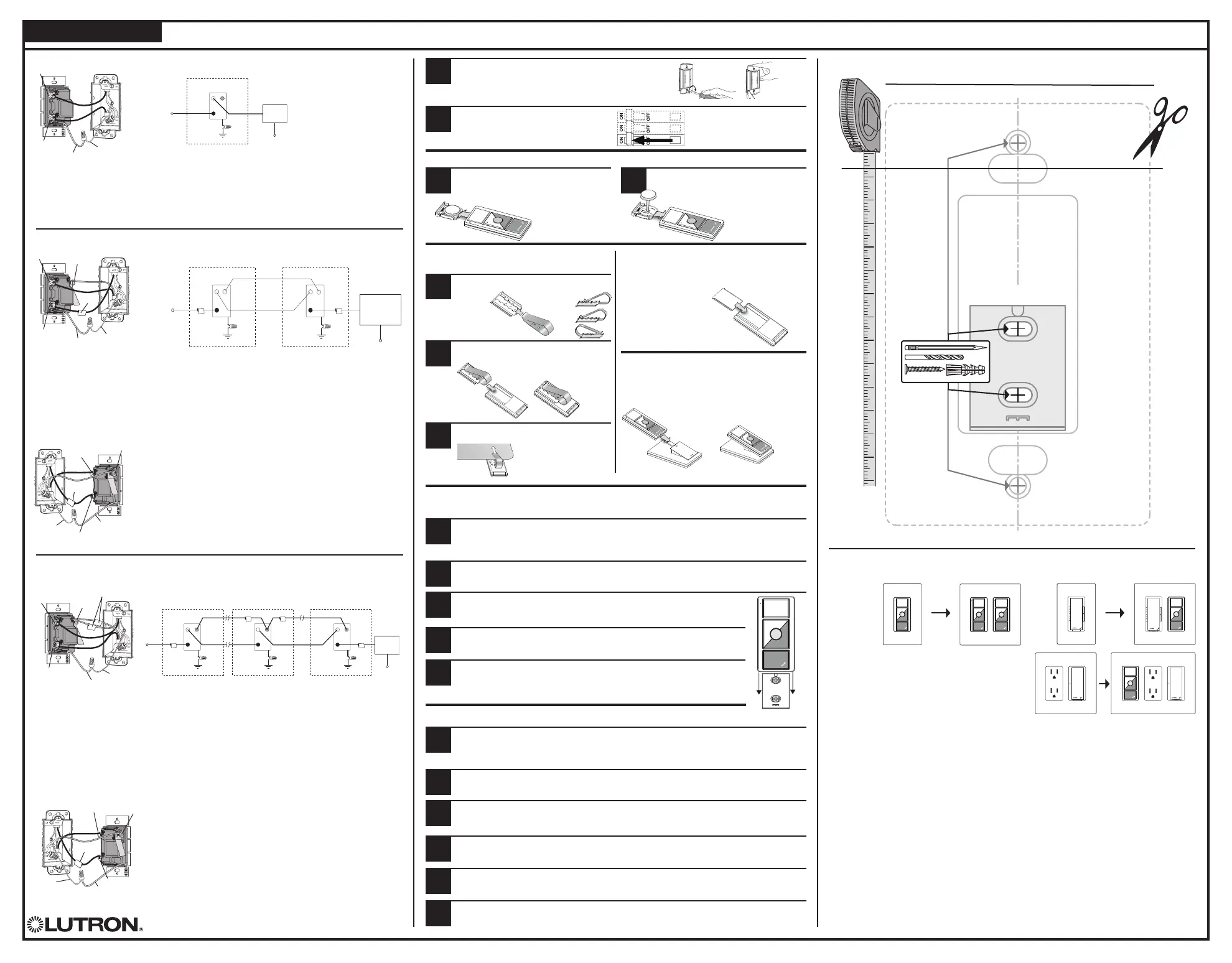
Carefully cut out the Template below along the outer dashed line and temporarily attach it to the
wall at the desired mounting location.
Note: To match location of existing wall controls, remove existing wallplate and measure height of
top screw.
Mark and drill the four
3
⁄16 in (35 mm) screw hole locations indicated on the Template.
Insert a Screw Anchor into each of the holes drilled in step 2, making sure they are flush with the wall.
Note: Template should be removed from wall before inserting anchors.
Mount the 1-gang wallplate with screws provided. Wallplate must be mounted after the Wireless
Controller is installed, not before.
Loosely mount the Wall Mount Backplate to the wall with screws. Check to make sure the Backplate
is level. Once level, tighten the screws fully.
Carefully cut out the Template below along the outer dashed line and temporarily attach it to the
wall at the desired mounting location.
Note: To match location of existing wall controls, remove existing wallplate and measure height
of top screw.
Remove the battery cover screw, then
gently slide the battery holder out of the
back of the Wireless Controller.
Mark and drill the two 3⁄16 in (35 mm) screw hole locations indicated within the Wall Mount
Backplate section (A) of the template.
Insert a Screw Anchor into each of the holes drilled in step 2, making sure they are
flush with the wall.
Note: Template should be removed from wall before inserting anchors.
Mounting a Wireless Controller Directly to a Wall Without
a Wallplate
Mounting a Wireless Controller in a 1-Gang Wallplate
Figure 3
Slide the metal Visor clip into the Visor
Backplate.
Loosely mount the Wall Mount Backplate to the wall with screws. Check to
make sure the Backplate is level. Once level, tighten the screws fully.
Slide Wireless Controller down onto the Wall Mount Backplate. (Figure 3)
Slide Wireless Controller down onto the Wall Mount Backplate. (Figure 3)
 Loading...