• ScrewTerminals:Usewith12AWG
(2.5mm
2
)or14AWG(1.5mm
2
)
solid copper wire only.DoNOT
usestrandedortwistedwire.
Wrapwirearoundscrew
terminal.Tightensecurelyto
5in-lb(0.55N
•
m).
b. WireConnectors:
Preparewires.Whenmaking
wireconnections,followthe
recommendedstriplengthsand
combinationsforthesuppliedwire
connector.
NOTE: Wire connectors provided are suitable
for copper wire only.
Wire Connector:
•
Stripinsulation3/8
in(10
mm)for14
AWG
(1.5mm
2
)or12AWG(2.5mm
2
)wire.
• Stripinsulation7/16in(11mm)for
18AWG(0.75mm
2
)or16AWG
(1.0mm
2
)wire.
•
Usetojoinoneortwo14
AWG(1.5
mm
2
)or
12AWG
(2.5mm
2
)wireswithone18AWG
(0.75mm
2
)or16AWG(1.0mm
2
)wire.
Forsingleandmulti-locationinstallations
seeWiring Diagrams.
4.Pushallwiresbackintothewallboxand
looselyfastenthecontroltothewallboxusing
thecontrolmountingscrewsprovided.Donot
pinchthewires.
5.AttachtheLutron®Claro®orSatinColors®
wallplateadapterandwallplate.See
Mounting Diagram.
a.Installwallplateadapterontofrontof
control(s).
b.Tightencontrolmountingscrewsuntil
wallplateadapterisflushtowall(donot
over-tighten).
c.Snapwallplateontowallplateadapter,and
verifythatcontrolisalignedproperly.
d.Ifcontrolsaremisaligned,loosenmounting
screwsappropriately.
6.Restorepower.Verifycorrectlocaloperation.
SeeDimmer/Fan OperationorSwitch
Operation.
* Dimmer:
RRD-6D, -6NA, -10D, -10ND
(120V~50/60Hz)
RRD-F6AN-DV (120/277V~50/60Hz)
* Switch:
RRD-
8ANS
(120V~50/60Hz)
RRD-8S-DV (120-277V~50/60Hz)
* Remote Switches:
RD-RS (120
V~
50/60Hz)
RD-RS-277 (277
V~
50/60Hz)
Installation Instructions
Please Read Before Installing
Multigang Installations
Inmultiganginstallations,severalcontrolsare
groupedhorizontallyinonemultigangwallbox.
Whencombiningcontrolsinawallbox,deratingis
required;however,noderatingisrequiredforfan
speedcontrolsandremotedimmers/switches.
Derating Chart
Control Load Type End of
Gang
Middle
of Gang
-6D
Incand. 500W 400W
MLV
400W/
500VA
300W/
400VA
-6NA
Incand./ELV 500W 400W
MLV
400W/
500VA
300W/
400VA
-10D,
-10ND
Incand. 800W 650W
MLV
600W/
800VA
500W/
650VA
-F6AN-DV*
3-wire
Fluorescent/
LED
5A 3.5A
50
ballasts
35
ballasts
-2ANF CeilingFan 2A 2A
-8ANS
Lighting 6.5A 5A
Motor
1/4HP
5.8A
1/6HP
4.4A
-8S-DV
Lighting
8A
(2-gang)
7A
(3-gang)
7A
Motor
1/10HP
3A
* Themaximumloadforthe-F6AN-DViseitherthe
deratedloadorthenumberofballasts,whicheveris
LESS.
NOTE: -8ANS,-RD-277and-RS-277controls
havefinsthatneedtoberemovedformultigang
installations.-6D,-6NA,-10D,-10ND,-F6AN-DV,
-2ANF,-8S-DV,-RDand-RScontrolsdo not
havefinsthatneedtoberemovedformultigang
installations.
Troubleshooting Guide
LutronElectronicsCo.,Inc.
7200SuterRoad|Coopersburg,PA18036-1299
P/N044-319Rev.B09/2012
Important Notes
WARNING – Entrapment Hazard –
Toavoidtheriskofentrapment,serious
injury,ordeath,thesecontrolsmustnot
beusedtocontrolequipmentwhichisnotvisible
fromeverycontrollocationorwhichcouldcreate
hazardoussituationssuchasentrapmentifoperated
accidentally.Examplesofsuchequipmentwhich
mustnotbeoperatedbythesecontrolsinclude(but
arenotlimitedto)motorizedgates,garagedoors,
industrialdoors,microwaveovens,heatingpads,
etc.Itistheinstaller’sresponsibilitytoensurethat
theequipmentbeingcontrolledisvisiblefromevery
controllocationandthatonlysuitableequipmentis
connectedtothesecontrols.Failuretodosocould
resultinseriousinjuryordeath.
Codes:Installinaccordancewithalllocaland
nationalelectricalcodes.
Grounding:Whenno“groundingmeans”existin
wallbox,the2011NationalElectricalCode®(NEC®)
allowsacontroltobeinstalledasareplacementif
1)anonmetallic,noncombustiblefaceplateisused
withnonmetallicattachmentscrewsor2)thecircuit
isprotectedbyagroundfaultcircuitinterrupter
(GFCI).Wheninstallingacontrolaccordingtothese
methods,caporremovegreenwirebeforescrewing
controlintowallbox.
Neutral Wire:-6NA,-10ND,-F6AN-DV,-2ANF,
and-8ANSrequire aneutralwireconnectioninthe
wallboxwherethedimmer/switch/fancontrolisto
beinstalled.Ifaneutralwireconnectionisnot
availableinthewallbox,contactalicensedelectrician
forinstallation.
Environment:Ambientoperatingtemperature:32°F
to104°F(0°Cto40°C),0%to90%humidity,non-
condensing.Indooruseonly.
Spacing:Ifmountingonecontrolaboveanother,
leaveatleast4
½
in(114mm)verticalspace
betweenthem.
Wallplates:Lutron®Claro®andSatinColors®
wallplatesarerecommendedforbestcolormatch
andaestheticappearance.Donotpaintcontrolsor
wallplates.
Cleaning:Toclean,wipewithacleandampcloth.DO
NOTuseanychemicalcleaningsolutions.
Wallboxes: Lutronrecommendsusing3
½
in
(89mm)deepwallboxesforeasierinstallation.
Severalcontrolsmaybeinstalledinonemultigang
wallbox.SeeDerating Chart.
Remotes:Useonlyremotedimmers
(-RD/-RD-277)andremoteswitches
(-RS/-RS-277)withdimmers/switches/fanspeed
controls.Upto9-RD/-RD-277or-RS/-RS-277
maybeusedwithcontrols.Mechanical3-or4-way
switcheswillnotwork.
RF Device Placement:RFdimmers/switchesand
fancontrolsmustbelocatedwithin30ft(9m)ofan
RFSignalRepeater.Remotedimmers/switchesare
notrequiredtobewithinaspecificrangeof
arepeater.
ForsystemswithanRFsignalrepeater,
RFdimmers/switches/fanspeedcontrolscannotbe
controlledbythesystemuntiltheyareprogrammed
inasystemaccordingtothesystemSetup Guide.
English
Lutron,Claro,SatinColors,Maestro,Hi-lume,Ecosystem,Eco-10,RadioRA,and)areregisteredtrademarksandRadioRA2,CompactSE,andFASSaretrademarksofLutronElectronicsCo.,Inc.
NECisaregisteredtrademarkoftheNationalFireProtectionAssociation,Quincy,Massachusetts.
©2012LutronElectronicsCo.,Inc.
Mounting Diagram
Control
Mounting
Screws
Wallbox
Control
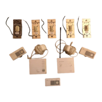
Included:
WireConnectors(1or5)
MountingScrews(2)
Adapter
Mounting
Screws
Wallplateadapterand
wallplatepurchased
separately.
Wallplate
Adapter
Wallplate
Technical Assistance:
U.S.A./Canada:1.800.523.9466|Mexico:+1.888.235.2910
Brazil:+55(11)3257-6745(M-F8:30to17:30BRT)|OtherCountries:+1.610.282.3800
24hoursaday,7daysaweek www.lutron.com
* Typical Power Consumption:
Dimmer / Switch / Fan Speed Control: 0.6 W
(Loadisoff,nightlightmodeenabled.)
Remote Dimmer / Switch: 0 W(Loadisoff.)
Installation
WARNING – Shock Hazard –
Toavoidtheriskofelectricshock
locateandremovefuseorlockcircuit
breakerintheOFFpositionbeforeproceeding.
WiringwithpowerONcouldresultinserious
injuryordeath.
1.TurnpowerOFFatfuseboxorcircuitbreaker.
2.Checktheinstallationforshortcircuitsbefore
installingcontrol(s).WithpowerOFF,install
standardmechanicalswitch(es)between
Hotandload.Restorepower.Iflightsor
fansdonotworkorabreakertrips,check
wiring.Correctwiringandcheckagain.Install
control(s)onlywhenshortisnolongerpresent.
WarrantyisvoidifcontrolisturnedONwitha
shortedcircuit.
3.Wirecontrolsaccordingtooneofthefollowing
options:
a. Terminals:Trimorstripwallboxwirestothe
lengthindicatedbythestripgaugeonthe
backofthecontrol.
• Push-InTerminals:Usewith
14AWG(1.5mm
2
)solid copper
wire only.DoNOTusestrandedor
twistedwire.
Insertwiresfully.Toreleasewire,
insertsmall,flatscrewdriverinto
slotbelowpush-interminal.
Pushscrewdriverinwhilepulling
wireout.
OR
Eachcontrol
hasinsidefins
removed
Controlatmiddle
ofganghasallfins
removed
Do Not removeoutsidefinson
controlsattheendofgang
SingleLocationInstallation
1
withoutNeutral
-6D,-10D(120V ~)
Wiring Diagram 1
Green
Ground
Hot/Live
Neutral
Load
Dimmer
120V~
50/60Hz
For system Setup Guide and tools visit
www.lutron.com/radiora2
Load Specifications
Control Load Type Min. Load Max. Load
-6D
1
Incand. 50W 600W
MLV
2
50W/VA
450W/
600VA
-6NA
1
Incand./
ELV
2
5W 600W
MLV
2
5W/VA
450W/
600VA
-10D
1
Incand. 50W 1000W
MLV
2
50W/VA
800W/
1000VA
-10ND
1
Incand. 10W 1000W
MLV
2
10W/VA
800W/
1000VA
-F6AN-DV
3,4,5
3-wire
Fluorescent/
LED
0.05A 6A
1ballast 60ballasts
-2ANF
6
CeilingFan 0.083A 2A
-8ANS
7
Lighting 10W/VA 8A
Motor 0.08A
1/4HP
5.8A
-8S-DV
8,9
Lighting 40W/VA 8A
Motor 0.4A
1/10HP
3A
-RD
10
SeeDimmer
8.3A
-RS
10
SeeSwitch
-RD-277
11
SeeDimmer
-RS-277
11
SeeSwitch
1 Dimmer Load Type: -6D,-10Dand-10NDaredesignedforuse
withpermanentlyinstalledincandescent,magneticlow-voltage,
ortungstenhalogenonly.
-6NAisdesignedforusewithpermanentlyinstalledincandescent,
electroniclow-voltage,magneticlow-voltage,ortungsten
halogenonly.
Donotinstalldimmerstocontrolreceptaclesormotor-operated
appliances.Donotmixincandescent,halogen,MLV,orELVload
typesonadimmer.
2 Low-Voltage Applications:Use-6D,-10Dand-10NDwith
magnetic(coreandcoil)low-voltagetransformersonly.Notfor
usewithelectronic(solid-state)low-voltagetransformers.
Use-6NAwithdimmableelectronic(solid-state)ormagnetic
(coreandcoil)transformers.
Operationofalow-voltagecircuitwithlampsinoperativeor
removedmayresultintransformeroverheatingandpremature
failure.Lutronstronglyrecommendsthefollowing:
a.Donotoperatelow-voltagecircuitswithoutoperativelampsin
place.
b.Replaceburned-outlampsasquicklyaspossible.
c.Usetransformersthatincorporatethermalprotectionorfused
transformerprimarywindingstopreventtransformerfailure
duetoovercurrent.
3 Fluorescent Dimmer Load Type:
-F6AN-DVisdesignedforusewithpermanentlyinstalled3-wire
120V~or277V~linevoltagecontrolfluorescentballastsorLED
drivers.UseonlywithHi-lume®,Hi-lume®3D,Hi-lume®A-Series,
CompactSE
™
,Eco-10®,orEcoSystem®(H3D-,FDB-,ECO-,
HL3-,EC5-,L3D).DoNOTusewithanyotherballastsordrivers.
Donotinstalltocontrolreceptaclesormotor-operatedappliances.
4 Power Boosters / Load Interfaces: -6NA,-10ND,-F6AN-DV,
and-8ANScanbeusedtocontrolpowerboosters/ load
interfaces.Foralistofcompatiblepowerboosters/ load
interfacesseeLutronP/N369225.
5 Maximum Load: Themaximumloadforthe-F6AN-DViseither
thederatedloadorthenumberofballasts,whicheverisLESS.
6 Ceiling Fan Application (-2ANF):
• Usetocontrolonepaddle-typeceilingfan
(permanentsplit-capacitor).
•Usetheceilingfan’spullchaintosetitsspeedtothe
highestsetting.
•Donotusetocontrolfansthatuseshaded-polemotors
(i.e.bathexhaustfans).
•Donotusetocontrolfansthathaveintegratedfanspeed
controls(i.e.fansthathavearemotecontrol),unlessthe
integratedcontrolisremovedfromtheceilingfan.
•Donotconnecttoanyothermotor-operatedapplianceorto
anylightingloadtype.
•Donotusetocontrolafanlightingload(i.e.lightkit).
7 Switch Load Type -8ANS: -8ANSisdesignedforusewith
permanentlyinstalled120V~incandescent,magnetic
low-voltage,electroniclow-voltage,orfluorescentloadsand
withmotorloadsupto1/4HP(5.8A).
8 Switch Load Type -8S-DV: -8S-DVisdesignedforuse
withpermanentlyinstalled120V~incandescent,magnetic
low-voltage,electroniclow-voltage,fluorescent,ormotorloads;
or277V~magneticlow-voltageorfluorescentloads.
9 Shunt Capacitor (included): Some-8S-DVinstallations
mayrequiretheuseofashuntcapacitor.Thisisespecially
necessaryforloadtypessensitivetoleakagecurrent(i.e.
fluorescentballasts).Ifloadflickers,installashuntcapacitor.
Forshunt
capacitorinstallationseeWiring Diagram 4 or 8.
10 120 V~ Remote Dimmer / Switch: -RDand-RSaredesigned
forusewith120V~dimmers/switches.
11 277 V~ Remote Dimmer / Switch: -RD-277and-RS-277are
designedforusewith277V~dimmers/switches.DoNOTuse
withmotorloads.
1
Whenusingcontrolsinsinglelocationinstallations,tightentheblueterminalwithoutanywiresattached.
DONOTconnecttheblueterminaltoanyotherwiringortoground.
2
ShuntcapacitormustbeinstalledinsidetheloadfixtureorinaseparateJ-box.
3
Installonly1dimmer/switch/fanspeedcontrolpercircuit.Upto9remotedimmers/switchesmaybeconnectedtoa
dimmer/switch/fanspeedcontrol.Totalblueterminalwirelengthmaybeupto250ft(76m).
4
Neutralwiredimmers/switches/fanspeedcontrolsmustbeconnectedontheLoadsideofamulti-locationinstallation.
Lamp Replacement
WARNING – Shock Hazard –For
anyprocedureotherthanroutine
lampreplacement,powermustbe
disconnectedatthemainelectricalpanel.
WorkingwithpowerONcouldresultin
seriousinjuryordeath.
Foryoursafetyduringroutinelamp
replacement,removepowerfromthefixture(s)
bymovingtheFASS
™
switchintotheOFF
positiononthedimmer/switchandallremote
dimmers/switches.
Symptom Probable Cause and Action
Light/fandoesn’tturn
ON/OFFwhentapswitch
ondimmer/switch/fan
speedcontrolorremote
dimmer/switchispressed
Power not present
•CircuitbreakerOFFortripped.Performshortcircuitcheck.
• FASS
™
isintheOFFposition.MoveFASS
™
totheONposition.
Checkthedimmer/switch/fanspeedcontrolandalloftheremote
dimmers/switches.SeeLamp Replacement.
Wiring
•Wiresshorted.Makesuretheblueterminalisnotgroundedorshortedto
anyotherwires.
•Wiringerror.Checkwiringtobesureitagreeswithinstallationinstructions
andwiringdiagrams.
•For-8S-DV,increaseloadtomeettheappropriateminimumload
requirementoruseshuntcapacitoror-8ANS.SeeLoad Specifications.
Load is less than minimum load requirement
•Makesuretheconnectedloadmeetstheappropriateminimumload
requirementforthatcontrol.SeeLoad Specifications.
•For-8S-DV,increaseloadtomeettheappropriateminimumload
requirementoruseshuntcapacitoror-8ANS.SeeLoad Specifications.
Lamps burned out or not installed
•Replaceorinstalllamps.
Dioded lamps
•Ifdiodedlampsarebeingused,replacewithnon-diodedlamps.
Fan setting
•Makesurethefanissettoitshighestspeedusingthepull-chain.
Fan Speed Control Wrong Load Type
•Makesurethatonlyasingleceilingpaddlefan(permanentsplit-capacitor
motor)ratedat2Aorlessisconnectedtothecontrol.
•Makesurethatnolightingload(i.e.lightkit)isconnectedtothecontrol.
Loadflickersortapswitch
doesnotworkevenifload
isgreaterthan40W
(-8S-DVonly)
Leakage current
•Installashuntcapacitor.SeeWiring Diagram 4 or 8.
LightturnsONandOFF
continuouslyorlightsturnON
whentapswitchispressed,
thenturnOFF
Load does not meet the minimum load requirement
•Increaseloadtomeettheappropriateminimumloadrequirementforthat
control.SeeLoad Specifications.
•Installashuntcapacitorwith-8S-DV.SeeSeeWiring Diagram 4 or 8.
•For-8S-DV,increaseloadtomeettheappropriateminimumload
requirementoruseshuntcapacitoror-8ANS.See
Load Specifications.
Loadflickers
(-8S-DVonly)
Load does not meet the minimum load requirement
•Increaseloadtomeettheappropriateminimumloadrequirementforthat
control.SeeLoad Specifications.
•Installashuntcapacitor.SeeWiring Diagram 4 or 8.
Lights/Fansdon’tturnON/
OFFfromakeypad
Improper programming
•ProgramaccordingtothesystemSetup Guide.
Out of RF range
•Repositiontobewithin30ft(9m)ofanRFsignalrepeater.
Wiring
•Wiresshorted.Makesuretheblueterminalisnotgroundedorshortedto
anyotherwires.
•Wiringerror.Checkwiringtobesureitagreeswithinstallationinstructions
andwiringdiagrams.
Wallplateiswarm Solid-state control dissipation
•Solid-statedimmers/switches/fanspeedcontrolsinternallydissipate
about2%ofthetotalconnectedload.Itisnormalfordimmers/
switches/fanspeedcontrolstofeelwarmtothetouchduringoperation.
NOTE: Refer to the system SetupGuide for additional troubleshooting suggestions.
SingleLocationInstallation
1
withoutNeutral
-8S-DVwithoptionalshuntcapacitor
2
(120-277V~)
Wiring Diagram 4
Brass
Black
Blue
1
Green
Ground
Hot/Live
Neutral
Load
Switch
120-277V~
50/60Hz
Shunt
Capacitor
2
Optional
SingleLocationInstallation
1
withNeutral
-F6AN-DV(120/277V~)
Wiring Diagram 3
Brass
Black
Blue
1
Green
Ground
Hot/Live
Neutral
Lutron®
Ballast/
LEDDriver
Lutron®
Ballast/
LEDDriver
Dimmer
120/277V~
50/60Hz
Black
Orange
White
Orange
Silver
Black
Orange
White
Multi-LocationDimmerInstallation
3
withNeutral
4
-F6AN-DVwith-RDor-RD-277
(120/277V~)
Dimmer
Remote DimmerRemote Dimmer
NOTE: Dimmermustbeinstalledon
theloadsideofthecircuit.
Brass/
Red
Brass/
Red
Black
Blue
Green
Ground
Hot/Live
Neutral
120/277V~
50/60Hz
Black
Orange
White
Black
Orange
White
Brass
Black
Blue
GreenGreen
GroundGround
Orange
Silver
Black
Blue
Status LEDs
Indicatelightlevel;glowssoftly
asnightlightwhenloadisoff
Tapswitch
Tapon/off
Dimming Rocker
PresstoBrighten
orIncreaseSpeed
PresstoDim
orDecreaseSpeed
FASS
™
Front
Accessible
Service
Switch
Dimmer/Fan Operation
Switch Operation
Status LED
Indicateslightstatus;glowssoftly
asnightlightwhenloadisoff
Tapswitch
Tapon/off
FASS
™
Front
Accessible
Service
Switch
OR
-RD-277or
-RS-277only
OFF ON
Multi-LocationInstallation
3
withNeutral
4
-6NA,-10ND,and-2ANFwithRD-RD,and-8ANSwithRD-RS(120V~)
Brass
Silver
Black
Blue
Green
Ground
Load
Brass
Black
Blue
Green
Ground
Remote Dimmer/
Remote Switch
120V~
50/60Hz
Brass
Black
Blue
Green
Ground
Hot/Live
Neutral
Remote Dimmer/
Remote Switch
Dimmer / Switch /
Fan Speed Control
Wiring Diagram 6
Wiring Diagram 7
Wiring Diagram 8
SingleLocationInstallation
1
withNeutral
-6NA,-10ND,-2ANFand-8ANS(120V ~)
Wiring Diagram 2
Dimmer/Switch/
Fan Speed Control
Twist wire
connector tight.
Multi-LocationInstallation
3
withoutNeutral
-6D,-10Dwith-RD(120V~)
Brass
Black
Blue
Green
Ground
Load
Dimmer
/
Remote Dimmer
3
Brass
Black
Blue
Green
Ground
Remote Dimmer
/
Dimmer
3
Brass
Black
Blue
Green
Ground
Hot/Live
Neutral
Remote Dimmer
/
Dimmer
3
120V~
50/60Hz
NOTE: Dimmermay be installed in
any location inthecircuit.
Return to Factory Settings
NOTE: Returningadimmer/switch/fanspeedcontoltoitsfactorysettingswillremoveitfromthesystemand
eraseallprogrammingfromit.
Step 1 : Tripletapthetapswitchonacontrol.DONOTreleaseafterthethirdtap.
Step 2 : Keepthetapswitchpressedonthethirdtap(forapproximately3seconds)untiltheLEDsonthedimmer
starttoscrollupanddownquickly,ortheLEDontheswitchflashesquickly
Step 3 : Releasethetapswitchandimmediatelytripletapthetapswitchagain.TheLEDsonthedimmerwillscroll
upanddownslowly.TheLEDontheswitchwillflashslowly.
Thecontrolhasnowbeenreturnedtofactorysettingsandneedstobereprogrammedintoasystem.
Warranty: SeetheWarrantyenclosedwiththeproduct,orvisit
www.lutron.com/TechnicalDocumentLibrary/Warranty.pdf
Multi-LocationInstallation
3
withoutNeutral
-8S-DVwith-RSor-RS-277andoptionalshuntcapacitor
2
(120– 277V~)
Black
Blue
Green
Ground
Load
Switch / Remote
Switch
3
Black
Blue
Green
Ground
Remote Switch /
Switch
3
Brass/
Red
Black
Blue
Green
Ground
Hot/Live
Neutral
Remote Switch /
Switch
3
NOTE: Switchmaybeinstalledinany
locationinthecircuit.
Shunt
Capacitor
2
120–277V~
50/60Hz
Optional
Brass/
Red
Brass/
Red
NOTE: Dimmermustbeinstalled
ontheloadsideofthecircuit.
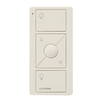
Designer-Style RF Maestro®
Dimmer
Shown
* Fan Speed Control:
RRD-2ANF (120
V~
50/60Hz)
* Remote Dimmers:
RD-RD (120
V~
50/60Hz)
RD-RD-277 (277
V~
50/60Hz)
Dimmer Switch
Remote
Switch
Remote
Dimmer
FanSpeed
Contol
Blue
1
Blue
1
Brass
Brass
Silver
Black
Black
Hot/Live
Neutral
120V~
50/60Hz
Green
Ground
Load
Wiring Diagram 5
Lutron®
Ballast/
LEDDriver
Lutron®
Ballast/
LEDDriver