UTILITY
EMERGENCY
SET
TEST
LOAD
1
5
6
2
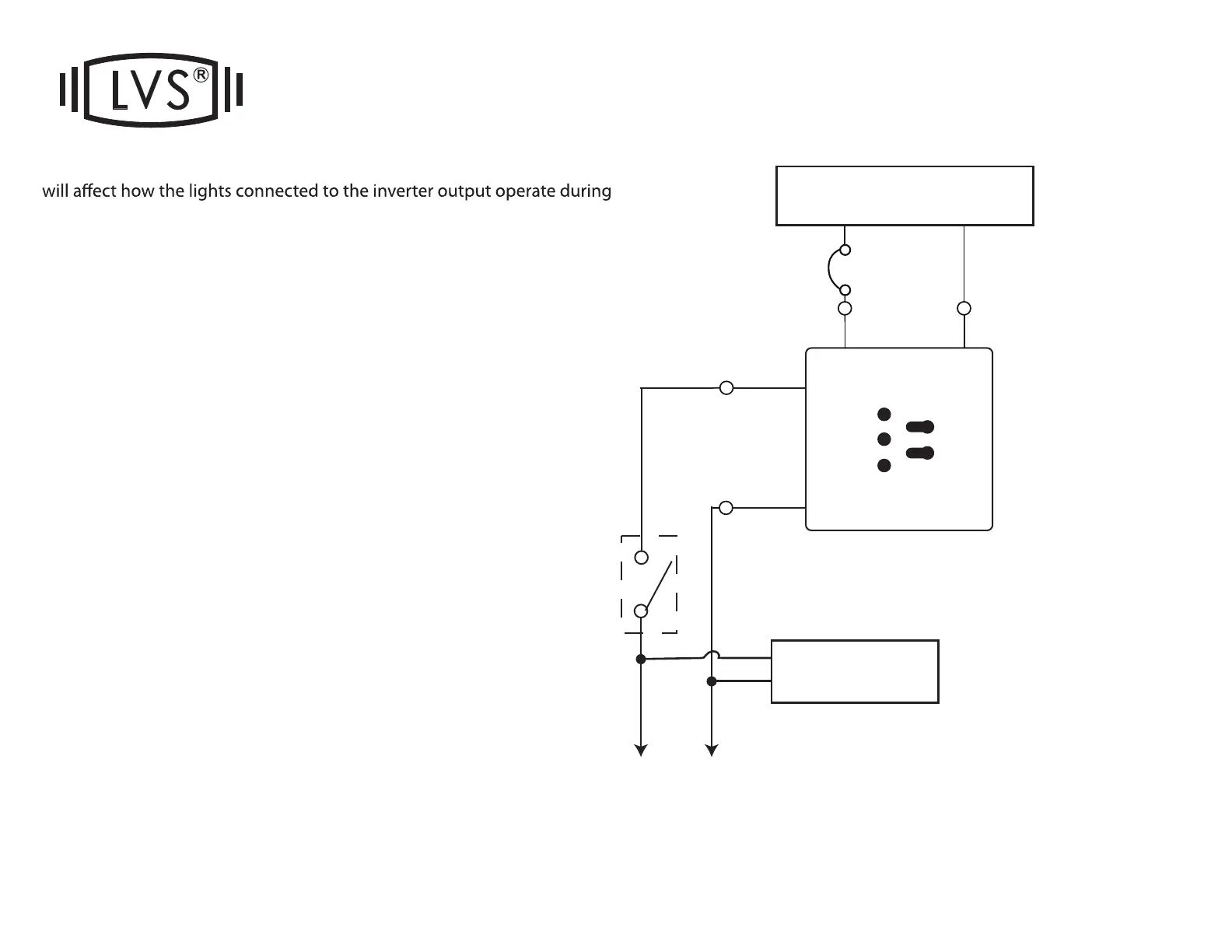
The wiring of the #1 wire on the transfer switch (red plastic box)
normal condition.
#1) (DEFAULT) NORMALLY-ON:
CONNECT #1 TO INPUT HOT
The emergency lights connected to the CEPS-A will be
ON at all times, during normal condition (24/7) and power
interruptions.
#2) NORMALLY-OFF:
CAP OFF #1
The emergency lights connected to the CEPS-A will be
OFF until a power interruption, at which time they will turn
ON.
#3) NORMALLY-SWITCHED:
CONNECT #1 to the load side of your wall switch, time
clock or occupancy sensor. DO NOT connect the light
itself to the switch or sensor or you will damage the invert-
er. The lights should be connected to “120V OUTPUT” or
“277V OUTPUT” Leads.
The emergency lights connected to the CEPS-A can then
be switched ON/OFF normally, until a power interruption,
at which time they will turn ON regardless of switch posi-
tion. Please note: Only one switch leg can be used per
inverter. If multiple switches are needed, wire the legs
inverter as NORMALLY-ON, and use LVS EPC relays.
HOT
INPUT
20A
Hot
Neutral
NEUTRAL
INPUT
TRANSFER SWITCH
 Loading...