Page 19
*
***
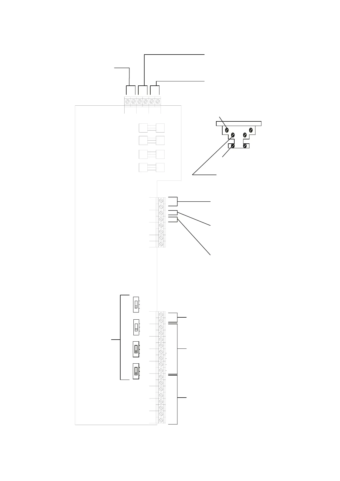
ZONE
321
ZONE ZONE
= 2= 1
4
ZONEZONE ZONE
TAMP= 4 = 3
ZONE ZONE
DETECTOR
F-AC
TRIGGER
STB
TXSET
LS
RX+VE +EXT-
2004/03
LS5000V10
TAMP
BELL BELL
F-BELLF-STROB
F-AUX
+12VDC-
BAT
14V
~~
+12VDC-
AUX
01 2
= 1
ZONE
102
ZONE= 2
102
ZONE
= 3
102
ZONE
= 4
JP3
JP4
JP5
JP6
AC
ZONE ‘=1’ ~ ZONE ‘=4’
Connect to two wired detector
ZONE ‘1’ ~ ZONE ‘4’
Connect to ‘zone’ terminal of
wired conventional detector or
Door/Window Contact
Detector
DETECTOR TEMP
Connect to wired detector
‘temper’ terminal
Switch the
number of two
wired detector
connected to
the zone.
14V AC
Connect to transformed 14V AC
BAT
Connect to 12V Rechargeable battery
L brown
G green/yellow
N blue
L: Connect to mains power live terminal
G: Connect to mains power ground terminal
N: Connect to mains power neutral terminal
AUX
Connect to the ‘power’
terminal of wired PIR or
external siren/strobe unit
BELL TEMP
Connect to the external siren/strobe temper
terminal
BELL TRIGGER
Connect to the trigger terminal of external siren
STB TRIGGER
Connect to the trigger terminal of external strobe
Wiring Diagram 3
 Loading...