EasyManua.ls Logo

Lytx DC-ACW-01 - User Manual

Lytx DC-ACW-01
20 pages
Print Icon
To Next Page IconTo Next Page
Loading...
Aux Camera
Quick Start Guide
Wi Fi Model Ethernet Model
Side Mount
DC-ACW-01 DC-ACE-01
Rear Mount
DC-ACW-02 DC-ACE-02
Model List:
Question and Answer IconNeed help?

Do you have a question about the Lytx DC-ACW-01 and is the answer not in the manual?

Overview

This document provides a Quick Start Guide for the Aux Camera, an AI IP camera available in both Wi-Fi and Ethernet models, designed for vehicle mounting. The camera is offered in two mounting configurations: Side Mount and Rear Mount.

Function Description

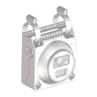
The Aux Camera is an AI IP camera designed for surveillance and monitoring applications, particularly in vehicles. It captures video signals and can transmit them via Wi-Fi or Ethernet, depending on the model. The camera integrates with the DriveCam/SurfSight devices for communication.

Important Technical Specifications

  • Models:
    • Wi-Fi Models: DC-ACW-01 (Side Mount), DC-ACW-02 (Rear Mount)
    • Ethernet Models: DC-ACE-01 (Side Mount), DC-ACE-02 (Rear Mount)
  • Wi-Fi Connectivity (for Wi-Fi models):
    • Supports Wi-Fi 802.11 b/g/n.
    • Wireless module complies with IEEE 802.11 b/g/n standard.
    • Can achieve speeds up to 72.2Mbps with a single stream in 802.11n draft, 54Mbps as specified in IEEE 802.11g, or 11Mbps for IEEE 802.11b to connect to the wireless LAN.
    • Operating Frequency and Output Power (WLAN): 2412 – 2472 MHz, 19.04dBm (EIRP).
  • Ethernet Connectivity (for Ethernet models):
    • Utilizes an M12 Ethernet D-Coded Cable for video signal transmission.
    • Pinout: Pin 1: TxData+, Pin 2: RxData+, Pin 3: TxData-, Pin 4: RxData-.
  • Power Supply:
    • Requires a 12V constant power source.
    • Red wire: Connects to 12V constant power source.
    • Black wire: Connects to clean CHASSIS GROUND.
  • Environmental Protection:
    • Designed with waterproofing and insulation measures for cables to protect them in humid environments.
    • Drip loops are recommended for cables in correct positions.
  • Compliance:
    • FCC Class A digital device, compliant with part 15 of the FCC Rules.
    • RED compliant (Directive 2014/53/EU).
    • Contains restricted substances as per environmental regulations (Lead, Mercury, Hexavalent chromium, Polybrominated biphenyls, Polybrominated diphenyl ethers).

Usage Features

  • Mounting Options:
    • Side Mounting: The camera is attached using hose clamps (1.5" or 4" depending on the model) to a side mirror bracket or similar structure. It features a rear clip and front clip for secure attachment.
    • Rear Mounting: The camera is attached to a rear frame plate using screws. It also features a rear clip and front clip.
  • Angle Adjustment:
    • Side Mounting: The camera's angle can be adjusted by releasing a Phillips screw (screw A) located in the bracket of the back mirror. After adjustment, the screws should be tightened. The camera allows for 360-degree rotation and tilt/pan adjustments.
    • Rear Mounting: The camera's angle can be adjusted by releasing Phillips screws (screw A and C) at both ends and tilting the camera. Screws B are used to fix the plate from a top view. After adjustment, all screws should be tightened.
  • Cable Connection:
    • Wi-Fi Model (Power-only installations): Connect the red wire to a 12V constant power source and the black wire to a clean chassis ground.
    • Ethernet Model (Video cable installation): Connect the power-cable first, then the video cable. If needed, an extension cable can be used. Ensure the O-ring for the waterproof connector is properly mounted, and all waterproof components are securely tightened to prevent loosening.
  • Reset Functionality:
    • A reset button is hidden in the bracket, under the bottom cover of the camera.
    • To access, remove the bottom cover using a Phillips screwdriver and use a pencil or pin to push the rubber button.
    • Soft Reset: Hold the reset button for over 10 seconds to reboot and reset all settings.
    • Hard Reset: Hold the reset button for over 3 seconds (but less than 10 seconds) to only reboot the camera.

Maintenance Features

  • Required Tools for Installation:
    • Wire cutter
    • Wire crimper
    • Voltmeter or Multi-meter
    • Cable ties
    • Electric tape
    • Vehicle manufacturer recommended tools
    • Tape measure
    • Phillips screwdriver
    • Flat-blade screwdriver
    • Marking pen
  • Cable Waterproofing and Insulation:
    • Ensure all cables are properly insulated and waterproofed to prevent damage from rain or water.
    • Apply one layer of insulation tape around each cable joint.
    • Stretch the waterproofing tape twice its original length and apply three layers from bottom to top, then from top to bottom, and from bottom to top again.
    • Stretch the insulation tape twice its original length and apply three layers from bottom to top, then from top to bottom, and from bottom to top again to tie the upper and lower ends with cable ties.
    • Cover the rest of the cabling in a conduit or with protective waterproof rubber tape.
    • Create a drip loop as shown in the manual to prevent water from reaching the lowest point of the cable.
  • Pre-Installation Check:
    • Verify that all screws are fully tightened.
    • Confirm the camera is securely installed to the mount or wall.
    • Check that the ambient temperature meets the device specifications.
    • Ensure insulation and waterproofing measures have been taken to protect cables in humid environments, and drip loops are in correct positions.
    • Confirm the camera powers on normally.
  • Caution:
    • Do not lift the camera by its cable.
    • Do not open the camera cover unless performing a reset or other specified maintenance.
  • FCC Compliance:
    • Any changes or modifications not expressly approved by the grantee of this device could void the user's authority to operate the equipment.
    • The device complies with Part 15 of the FCC Rules. Operation is subject to two conditions: (1) this device may not cause harmful interference, and (2) this device must accept any interference received, including interference that may cause undesired operation.
    • RF exposure warning: The equipment must be installed and operated with a minimum distance of 20 cm between the radiator and your body. This transmitter must not be co-located or operating in conjunction with any other antenna or transmitter.

Lytx DC-ACW-01 Specifications

General IconGeneral
BrandLytx
ModelDC-ACW-01
CategoryDigital Camera
LanguageEnglish