Installation 25/56
RE 93221-01-B/07.2013, A22VG Series 40, Bosch Rexroth AG
▶ The case drain fluid in the housing must be directed to the reservoir via the
highest case drain port. Use the line size which is appropriate for the port.
▶ Avoid using a check valve in the reservoir line.
▶ To achieve favorable noise values, decouple all connecting lines from all vibration-
capable components (e.g. reservoir) using elastic elements.
▶ Make sure that the suction, reservoir and return lines lead into the reservoir
below the minimum fluid level in all operating conditions. This will prevent air
from being drawn in and foam from being formed.
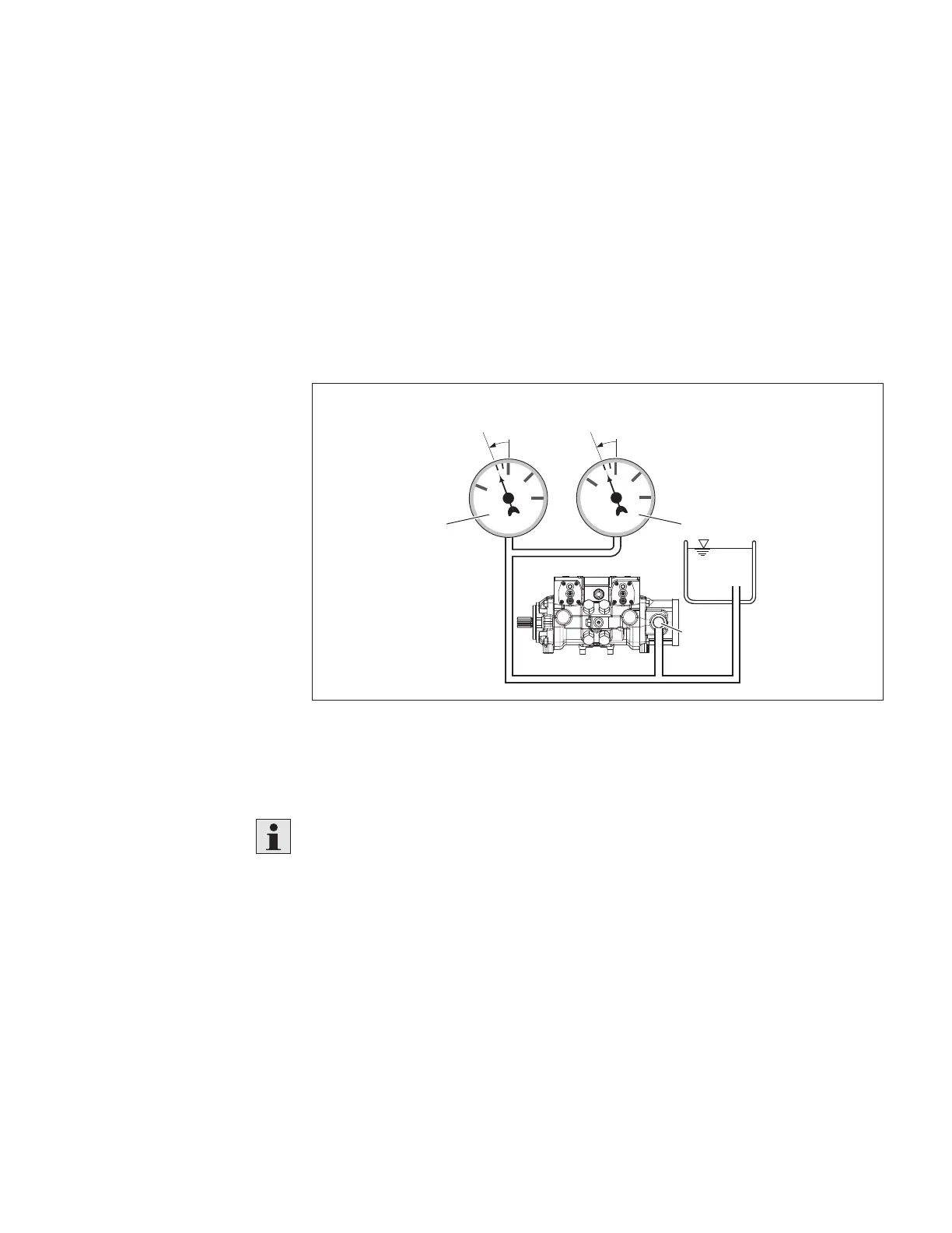
▶ Make sure that a minimum suction pressure of 0.8 bar absolute is present at port
S during operation (0.5 bar absolute for cold starts) in all installation positions
and installation locations for the axial piston pump, see Fig. 6. Please refer to the
data sheet for further pressure values.
-0.2
0.8 abs.
1
2
3
0
0
1
2
-1
21
S
Fig. 6: Suction pressure
1 Absolute pressure gauge
2 Standard pressure gauge (relative)
The suction conditions improve with below-reservoir installation.
▶ Make sure that the working environment at the installation site is fully free of
dust and foreign substances. The axial piston unit must be installed in a clean
condition. Dirt contamination in the hydraulic fluid can seriously impair the
function and service life of the axial piston unit.
▶ Use lint-free cloths for cleaning.
▶ Use suitable mild detergents to remove lubricants and other difficult-to-remove
contamination. Cleaning agents must not enter the hydraulic system.
 Loading...