26/56 Installation
Bosch Rexroth AG, A22VG Series 40, RE 93221-01-B/07.2013
7.3 Installation position
The following installation positions are permissible. The shown piping layout
illustrates the basic layout.
If it is not possible to fill the stroking chambers via X
1
to X
6
in the final installation
position, this must be done prior to installation.
In order to prevent unexpected activation behavior and damage, the stroking
chambers must be air bled via ports X
1
, X
2
or X
5
, X
6
or X
3
, X
4
, according to their
installation position.
Please note that with HT control, port X
1
, X
2
is omitted and is replaced by X
5
, X
6
.
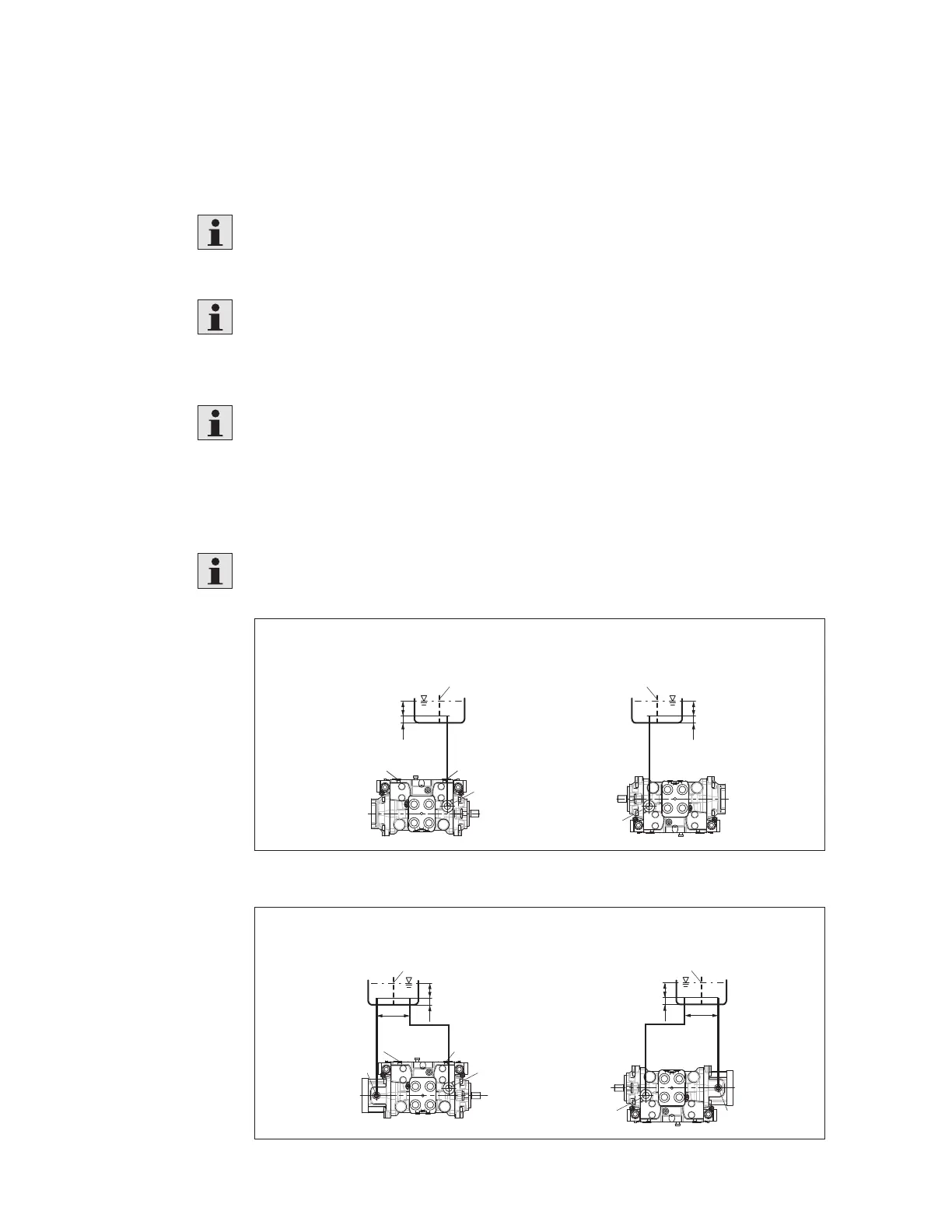
7.3.1 Below-reservoir installation (standard)
Below-reservoir installation means that the axial piston unit is installed outside of
the reservoir below the minimum fluid level.
Recommended installation position: 1 and 2 (without boost pump)
3 and 4 (with boost pump)
T
h
t min
h
min
X
1
, X
2
, R R, X
1
, X
2
SB
T
h
t min
h
min
SB
12
Fig. 7: Below-reservoir installation A22VG without boost pump, installation position 1-2
34
SB
h
t min
h
min
a
min
ST
SB
X
1
, X
2
, R R, X
1
, X
2
h
t min
h
min
a
min
TS
Fig. 8: Below-reservoir installation: A22VG with boost pump, installation position 3-4
 Loading...