Installation 27/56
RE 93221-01-B/07.2013, A22VG Series 40, Bosch Rexroth AG
R
Air bleed port
h
min
Minimum required spacing to
reservoir bottom(100mm)
S
Suction port
a
min
When designing the reservoir, ensure
adequate distance between the
suction line and the case drain line.
This prevents the heated, return flow
from being drawn directly back into
the suction line.
T
Reservoir port (case drain)
SB
Baffle (baffle plate)
h
t min
Minimum required immersion depth
(200 mm)
Table 8: Below-reservoir installation
Installation position Air bleeding the
housing
Air bleed
Stroking chamber
Filling
1 (drive shaft, horizontal)
R X
1
, X
2
T + X
1
+ X
2
2 (drive shaft, horizontal) – –T
3 (drive shaft, horizontal)
R X
1
, X
2
S + T + X
1
+ X
2
4 (drive shaft, horizontal) – – S + T
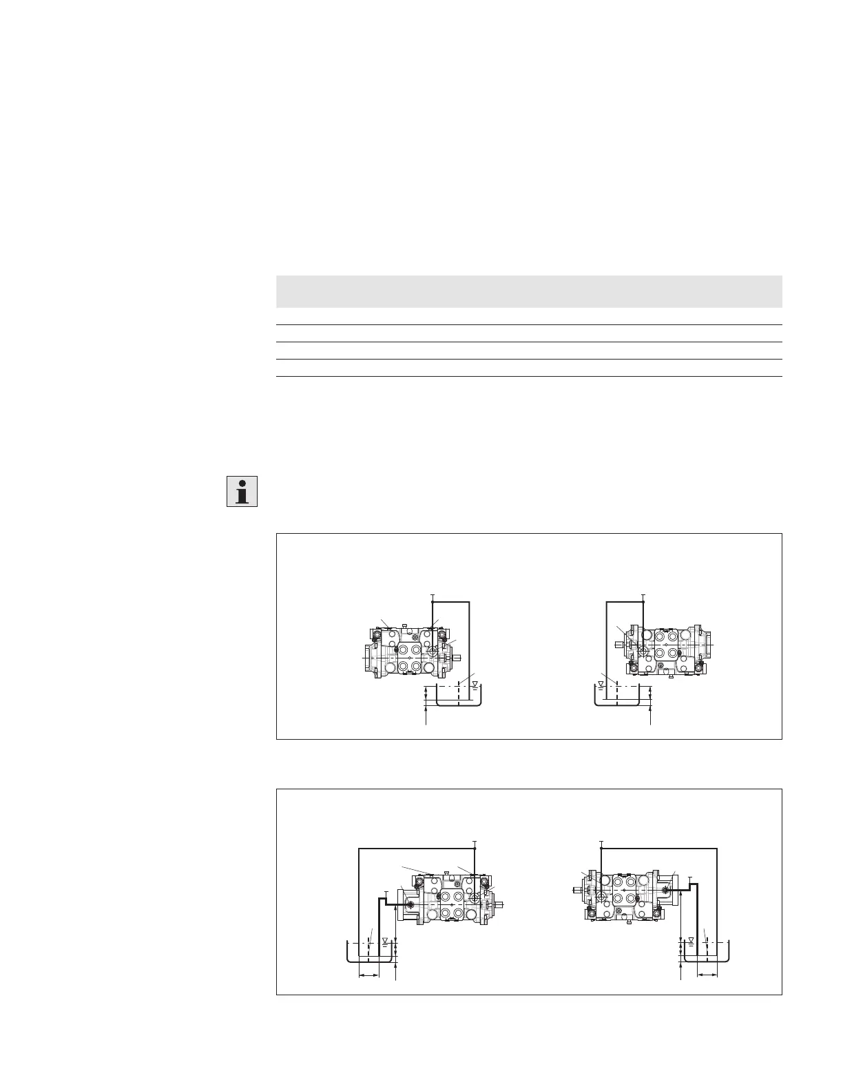
7.3.2 Above-reservoir installation
Above-reservoir installation means that the axial piston unit is installed above the
minimum fluid level of the reservoir.
Observe the maximum permissible suction height h
Smax
=800mm.
The permissible suction height h
S
is derived from the total pressure loss.
h
t min
h
min
L
1
SB
X
1
, X
2
, R R, X
1
, X
2
T
56
h
t min
h
min
L
1
SB
T
Fig. 9: Above-reservoir installation A22VG without boost pump, installation position 5-6
78
SB
h
t min
h
min
h
S max
a
min
TS
L
2
X
1
, X
2
, R R, X
1
, X
2
L
1
SB
h
t min
h
min
h
S max
a
min
TS
L
2
L
1
Fig. 10: Above-reservoir installation A22VG with boost pump, installation position 7-8
 Loading...