28/56 Installation
Bosch Rexroth AG, A22VG Series 40, RE 93221-01-B/07.2013
L
Filling / air bleed
h
min
Minimum required spacing to
reservoir bottom(100mm)
R
Air bleed port
h
S max
Maximum permissible suction height
(800mm)
S
Suction port
a
min
When designing the reservoir, ensure
adequate distance between the
suction line and the case drain line.
This prevents the heated, return flow
from being drawn directly back into
the suction line.
T
Reservoir port (case drain)
SB
Baffle (baffle plate)
h
t min
Minimum required immersion depth
(200 mm)
Table 9: Above-reservoir installation
Installation position Air bleeding the
housing
Air bleed
Stroking chamber
Filling
5 (drive shaft, horizontal)
R X
1
, X
2
L
1
+ X
1
+ X
2
6 (drive shaft, horizontal) L
1
– L
1
7 (drive shaft, horizontal) R + L
2
(S) X
1
, X
2
L
1
+ L
2
(S) + X
1
+ X
2
8 (drive shaft, horizontal) L
1
+ L
2
(S) – L
1
+ L
2
(S)
7.4 Installing the axial piston unit
7.4.1 Preparation
1. Compare the material number and designation (ordering code) with the details in
the order confirmation.
If the material number for the axial piston unit does not correspond to the one in
the order confirmation, contact Bosch Rexroth Service for clarification, see
chapter 10.5 “Spare parts” on page45.
2. Before installing, completely empty the axial piston unit to prevent any mixing
with the hydraulic fluid used in the machine/system.
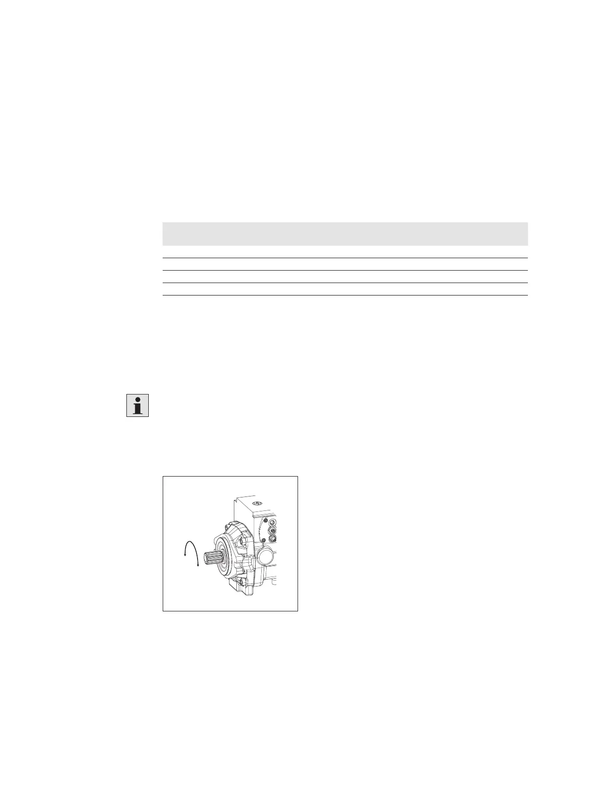
L
R
Fig. 11: Direction of rotation
L
Counter-clockwise
R
Clockwise
3. Check the direction of rotation of the axial piston unit (on the name plate) and
make sure that this corresponds to the direction of rotation of the output/drive
shaft of the machine/system.
 Loading...