EasyManua.ls Logo

M-system M5 Series - User Manual

M-system M5 Series
5 pages
Print Icon
To Next Page IconTo Next Page
Loading...
MODEL: M5MV
Super-mini Terminal Block Signal Conditioners M5-UNIT
SIGNAL TRANSMITTER
(narrow span input)
Functions & Features
• Converts a narrow span (≤ 100 mV DC) input into an
isolated DC signal
• High-density mounting
• Power LED
• CE marking for 24 V DC power
25 (.98)
97
(3.82)
41 (1.61)
mm (inch)
MODEL: M5MV-[1][2]-[3][4]
ORDERING INFORMATION
Specify a code from below for each [1] through [4].
• Code number: M5MV-[1][2]-[3][4]
(e.g. M5MV-14W-R/K/Q)
Specify variables.
• Special input and output range (For codes Z & 0)
• Specify the specification for option code /Q
(e.g. /C01)
[1] INPUT
Current
K: 0 – 100 μA DC (Input resistance 1000 Ω)
Z: Specify current (See INPUT SPECIFICATIONS)
Voltage
1: 0 – 10 mV DC (Input resistance 10 kΩ min.)
15: 0 – 50 mV DC (Input resistance 10 kΩ min.)
0: Specify voltage (See INPUT SPECIFICATIONS)
[2] OUTPUT
Current
A: 4 – 20 mA DC (Load resistance 550 Ω max.)
Z: Specify current (See OUTPUT SPECIFICATIONS)
Voltage
18: 0 – 80 mV DC (Load resistance 100 kΩ min.)
(CE not available)
4: 0 – 10 V DC (Load resistance 1000 Ω min.)
5: 0 – 5 V DC (Load resistance 500 Ω min.)
6: 1 – 5 V DC (Load resistance 500 Ω min.)
4W: -10 – +10 V DC (Load resistance 8000 Ω min.)
5W: -5 – +5 V DC (Load resistance 4000 Ω min.)
0: Specify voltage (See OUTPUT SPECIFICATIONS)
[3] POWER INPUT
AC Power
M: 85 – 264 V AC (Operational voltage range 85 – 264 V,
47 –66 Hz)
(CE not available)
DC Power
R: 24 V DC
(Operational voltage range 24 V ±10 %, ripple 10 %p-p max.)
[4] OPTIONS (multiple selections)
Response Time (0 – 90 %)
blank: Standard (≤ 0.5 sec.)
/K: Fast Response (Approx. 25 msec.)
Other Options
blank: none
/Q: Option other than the above (specify the specification)
SPECIFICATIONS OF OPTION: Q
COATING (For the detail, refer to M-System's web site.)
/C01: Silicone coating
/C02: Polyurethane coating
/C03: Rubber coating
GENERAL SPECIFICATIONS
Construction: Terminal block
Connection: M3.5 screw terminals (torque 0.8 N·m)
Screw terminal: Nickel-plated steel
Housing material: Flame-resistant resin (black)
Isolation: Input to output to power
Zero adjustment: -2 to +2 % (front)
Span adjustment: 98 to 102 % (front)
Power LED: Green light turns on when the power is supplied.
INPUT SPECIFICATIONS
DC Current: Input resistor incorporated
Specify input resistance value for code Z.
(R ≤ 0.125 W ÷ [F.S. Current]
2
)
DC Voltage: -100 – +100 mV DC
Minimum span: 5 mV
Offset: Max. 1.5 times span
Input resistance: ≥ 10 kΩ
OUTPUT SPECIFICATIONS
■ DC Current: 0 – 20 mA DC
Minimum span: 1 mA
Rugghölzli 2
CH - 5453 Busslingen
Tel. +41 (0)56 222 38 18
Fax +41 (0)56 222 10 12
mailbox@sentronic.com
www.sentronic.com
Produkte, Support und Service
SEN
TRONIC
AG
Question and Answer IconNeed help?

Do you have a question about the M-system M5 Series and is the answer not in the manual?

Summary

SIGNAL TRANSMITTER (narrow span input)

Functions & Features

Describes product capabilities like isolated DC signal and high-density mounting.

Ordering Information

Details on specifying the model code for input, output, power, and options.

General Specifications

Covers construction, connection, housing, isolation, and adjustments.

Input;Output Specifications

Details specific parameters for DC current/voltage inputs and outputs.

INSTALLATION & PERFORMANCE

Power Consumption

Details power usage for AC and DC inputs.

Operating Conditions

Covers operating temperature and humidity limits.

Performance Characteristics

Outlines accuracy, temp coefficient, and voltage effects.

Standards & Approvals

Lists CE conformity and relevant EMC standards.

DIMENSIONS & SCHEMATICS

External Dimensions

Provides physical dimensions in mm and inches.

Connection Diagram

Illustrates wiring for input, output, and power.

INSTRUCTION MANUAL

Before Use

Advises checking package contents and contacting support if needed.

Points of Caution

Highlights EC directives, power input, general precautions, environment, and wiring.

Component Identification

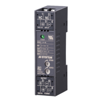
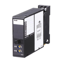
Identifies key parts of the unit like body, LED, and adjustments.

Installation Procedure

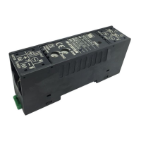
Explains how to mount and remove the unit from a DIN rail.

TERMINAL CONNECTIONS & CHECKING

Terminal Connections

Shows how to connect the unit via terminal blocks.

Checking Procedure

Outlines steps to verify wiring, power, input, and output.

Adjustment Procedure

Details how to calibrate zero and span settings.

Maintenance & Warranty

Explains calibration, warranty terms, and contact information.

Overview

M5MV Super-mini Terminal Block Signal Conditioner

The M5MV is a super-mini terminal block signal conditioner designed to convert narrow span inputs (≤ 100 mV DC) into an isolated DC signal. This device is characterized by its high-density mounting capability, a power LED indicator, and CE marking for 24 V DC power, making it suitable for various industrial applications requiring precise signal conditioning in a compact form factor.

Ordering Information

The M5MV model is specified using a series of codes: M5MV-[1][2]-[3][4].

[1] Input:

  • Current:
    • K: 0 – 100 μA DC (Input resistance 1000 Ω)
    • Z: Specify current (refer to INPUT SPECIFICATIONS for details).
  • Voltage:
    • 1: 0 – 10 mV DC (Input resistance 10 KΩ min.)
    • 15: 0 – 50 mV DC (Input resistance 10 KΩ min.)
    • 0: Specify voltage (refer to INPUT SPECIFICATIONS for details).

[2] Output:

  • Current:
    • A: 4 – 20 mA DC (Load resistance 550 Ω max.)
    • Z: Specify current (refer to OUTPUT SPECIFICATIONS for details).
  • Voltage:
    • 18: 0 – 80 mV DC (Load resistance 100 KΩ min.) (CE not available)
    • 4: 0 – 10 V DC (Load resistance 1000 Ω min.)
    • 5: 0 – 5 V DC (Load resistance 500 Ω min.)
    • 6: 1 – 5 V DC (Load resistance 500 Ω min.)
    • 4W: -10 – +10 V DC (Load resistance 8000 Ω min.)
    • 5W: -5 – +5 V DC (Load resistance 4000 Ω min.)
    • 0: Specify voltage (refer to OUTPUT SPECIFICATIONS for details).

[3] Power Input:

  • AC Power:
    • M: 85 – 264 V AC (Operational voltage range 85 – 264 V, 47 – 66 Hz) (CE not available)
  • DC Power:
    • R: 24 V DC (Operational voltage range 24 V ±10%, ripple 10 %p-p max.)

[4] Options (multiple selections):

  • Response Time (0 - 90%):
    • blank: Standard (≤ 0.5 sec.)
    • /K: Fast Response (Approx. 25 msec.)
  • Other Options:
    • blank: none
    • /Q: Option other than the above (specify the specification)

Specifications of Option: Q (Coating)

For detailed information on coating, refer to M-System's website.

  • /C01: Silicone coating
  • /C02: Polyurethane coating
  • /C03: Rubber coating

General Specifications

  • Construction: Terminal block
  • Connection: M3.5 screw terminals (torque 0.8 N·m)
  • Screw terminal: Nickel-plated steel
  • Housing material: Flame-resistant resin (black)
  • Isolation: Input to output to power
  • Zero adjustment: -2 to +2% (front)
  • Span adjustment: 98 to 102% (front)
  • Power LED: Green light turns on when the power is supplied.

Input Specifications

  • DC Current: Input resistor incorporated. Specify input resistance value for code Z (R ≤ 0.125 W ÷ [F.S. Current]²).
  • DC Voltage: -100 – +100 mV DC
  • Minimum span: 5 mV
  • Offset: Max. 1.5 times span
  • Input resistance: ≥ 10 KΩ

Output Specifications

  • DC Current: 0 - 20 mA DC
  • Minimum span: 1 mA
  • Offset: Max. 1.5 times span
  • Load resistance: Output drive 11 V max.
  • DC Voltage: 0 - 10 V DC
  • Minimum span: 1 V
  • Offset: Max. 1.5 times span
  • Load resistance: Output drive 10 mA max.; at ≥ 1 V

Installation

  • Power Consumption:
    • AC: Approx. 2 VA at 100 V, Approx. 3 VA at 200 V, Approx. 3 VA at 264 V
    • DC: Approx. 2 W
  • Operating temperature: -5 to +55°C (23 to 131°F)
  • Operating humidity: 0 to 90 %RH (non-condensing)
  • Mounting: DIN rail
  • Weight: 80 g (2.8 oz)

Performance in Percentage of Span

  • Accuracy: ±0.1%
  • Temp. coefficient: ±0.015 %/°C (±0.008 %/°F)
  • Line voltage effect: ±0.1% over voltage range
  • Insulation resistance: ≥ 100 MΩ with 500 V DC
  • Dielectric strength (input to output to power to ground):
    • DC powered: 2000 V AC @1 minute
    • AC powered: 1500 V AC @1 minute

Standards & Approvals

  • CE conformity:
    • EMC Directive (2004/108/EC)
    • EMI EN 61000-6-4: 2007
    • EMS EN 61000-6-2: 2005

Front View

The front panel features:

  • Power LED
  • Span Adjustment
  • Zero Adjustment

Dimensions

  • Unit: mm (inch)
  • Overall dimensions: 25 (.98) W x 97 (3.82) H x 41 (1.61) D
  • DIN rail mounting: 35mm wide
  • No extra space is needed between units when mounting.

Schematic Circuitry & Connection Diagram

The device includes an input section with a low drift amplifier, an isolation barrier, and an output driver. Power is supplied to terminals 7 (U+) and 8 (V-). Input signals connect to terminals 3 (+) and 4 (-), while output signals connect to terminals 5 (+) and 6 (-). An input shunt resistor is incorporated for current input.

Points of Caution

  • Conformity with EC Directives:
    • Equipment must be mounted inside a panel.
    • Insert a noise filter for power source, input, and output (e.g., COSEL NAC-06-472, TDK ZCAT 3035-1330).
    • Installation environments may affect protection level; review CE requirements and employ additional protective measures.
  • Power Input Rating & Operational Range:
    • Confirm power input rating marked on the product.
    • 85-264V AC rating: 85-264V, 47-66 Hz, approx. 2-3VA.
    • 24V DC rating: 24V ±10%, approx. 2W.
  • General Precautions:
    • Turn off power supply and input signal before removing or mounting the unit.
  • Environment:
    • Indoor use only.
    • Install inside proper housing with sufficient ventilation if heavy dust or metal particles are present.
    • Avoid continuous vibration or physical impact.
    • Environmental temperature: -5 to +55°C (23 to 131°F) with relative humidity 0 to 90% RH.
  • Wiring:
    • Do not install cables (power supply, input, output) close to noise sources (relay drive cable, high frequency line, etc.).
    • Do not bind these cables with noisy ones or install them in the same duct.
    • Install lightning surge protectors for wires connected to remote locations.
    • For 24V DC power supply line, choose a surge protector with a maximum surge voltage 40V or less between lines (e.g., M-System MDP-D24).
  • Warm-up: The unit is designed to function as soon as power is supplied, but a warm-up of 20 minutes is required for satisfying complete performance.

Installation Procedure

Set the unit so that its DIN rail adapter is at the bottom.

Mounting the Unit on a DIN Rail:

  1. Hang the upper hook at the rear side of the unit on the DIN rail.
  2. Push in the lower part while keeping pressing the unit to the DIN rail.

Removing the Unit:

  1. Push down the DIN rail adapter using a minus screwdriver.
  2. Pull out the lower part of the unit.
  3. Remove the upper part from the DIN rail.

Checking

  1. Terminal wiring: Check that all cables are correctly connected according to the connection diagram.
  2. Power input voltage: Check voltage across terminals 7-8 with a multimeter.
  3. Input: Check that the input signal is within 0-100% of the full-scale.
  4. Output: Check that the load resistance meets the described specifications.

Adjustment Procedure

The unit is factory calibrated to meet ordered specifications, so calibration is usually not needed. For matching the signal to a receiving instrument or for regular calibration, adjust the output as explained below.

How to Calibrate the Output Signal: Use a signal source and measuring instruments of sufficient accuracy. Turn on the power supply and warm up for more than 20 minutes.

  1. ZERO: Apply 0% input and adjust output to 0%.
  2. SPAN: Apply 100% input and adjust output to 100%.
  3. Check ZERO adjustment again with 0% input.
  4. If the ZERO value is changed, repeat steps 1-3.

Maintenance

Calibration: Warm up the unit for at least 20 minutes. Apply 0%, 25%, 50%, 75%, and 100% input signal. Check that the output signal for the respective input signal remains within the accuracy described in the data sheet. If the output is out of tolerance, recalibrate the unit according to the "ADJUSTMENT PROCEDURE" explained above.

M-System Warranty

M-System warrants new products to be free from defects in materials and workmanship for 36 months from the original purchase date, provided normal operating conditions and proper maintenance. M-System's sole liability and purchaser's exclusive remedies are, at M-System's option, repair, replacement, or refund of the purchase price of any defective product. To claim under this warranty, the purchaser must return the defective product, at its expense, to the specified address with a copy of the original sales invoice. This warranty is exclusive and in lieu of all other warranties, express or implied, including any implied warranties of merchantability or fitness for a particular purpose. M-System shall have no liability for consequential, incidental, or special damages of any kind.

M-system M5 Series Specifications

General IconGeneral
BrandM-system
ModelM5 Series
CategoryTransmitter
LanguageEnglish

Related product manuals