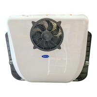
The Mabru Rooftop RVSC 12000 DC 12V is an air conditioning unit designed for RVs, trucks, vans, buses, campers, mobile homes, and similar applications. It is engineered to be sleek, aerodynamic, aesthetically pleasing, and highly efficient for 12V/24V systems. The unit provides cool, fresh air within 15 seconds, creating a comfortable interior environment.
Important Technical Specifications:
- Model: T2000-24V (DC24V) / T2000-12V (DC12V)
- Rated Voltage: DC24V / DC12V
- Evaporator Air Volume: 600m³/h (DC24V) / 550m³/h (DC12V)
- BTU: 12300 BTU
- Condenser Air Volume: 2200m³/h (DC24V) / 2000m³/h (DC12V)
- Rated Wattage: 850W (DC24V) / 700W (DC12V)
- Refrigerant: R134A
- Size (Roof): 38.19 (L) x 33.78 (W) x 6.5 (H) inches
- Max Size (Inside): 36.61 (L) x 21.26 (W) inches
- Min Size (Inside): 18.11 (L) x 11.42 (W) inches
- Minimum Size Hole: 14"x14" or 14.5/8"x20.1/8"
- Weight: 59 LB
- Shipping Weight: 76 LB
Current Consumption at 12V:
- High speed (Max): 54.4 Amp (HB), 51.2 Amp (MB), 48.2 Amp (LB)
- Medium speed: 46.2 Amp (HB), 43 Amp (MB), 40.8 Amp (LB)
- Low speed (Eco): 34.2 Amp (HB), 25.2 Amp (MB), 22.5 Amp (LB)
Usage Features:
The unit features an intuitive control panel and remote operation.
Components and Controls:
- Outdoor Unit Cover: Protects external components.
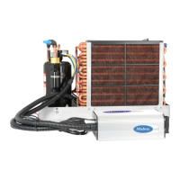
- Condenser Fan: Facilitates heat exchange in the outdoor unit.
- Outdoor and Indoor Unit Separator/Mounting Plate: Connects and secures the indoor and outdoor sections.
- Skylight Panel: Allows light into the interior.
- Return Inlet: Where air is drawn into the unit for cooling.
- Display: Shows current settings and status.
- Supply Outlet: Where cooled air is discharged.
- LED Lights: Provides interior illumination.
- Infrared Receiver: For remote control operation.
12V AC Controls:
- On/Off Switch: Powers the unit on or off.
- Blower Speed Control: Adjusts the fan speed (indicated by a fan icon).
- Mode Selector (M button): Cycles through three power modes:
- Max: Highest energy consumption, fastest cooling.
- Normal Cooling Mode (fan icon): Medium cooling, recommended for routine use.
- Low/Economy Mode (ECO): Energy-saving mode, minimum amp draw, less efficient cooling.
- Temperature Increase/Decrease Buttons (up/down arrows): Adjusts the set temperature.
- A/C On/Off Indicator: Lights up when the AC function is active.
- Fan On/Off Indicator: Lights up when the fan is active.
- System Inspect Indicator: Indicates system status or faults.
Display Features:
- The display always shows the set temperature in Celsius (range 5-40°C).
- To view current voltage: Press and hold the "M" button for 6 seconds. The voltage value will appear. The unit returns to the main menu automatically after 6 seconds of no button presses.
- To view current inlet temperature: Press and hold the "↑" symbol for 6 seconds.
- To view current outlet temperature: Press and hold the "↓" symbol for 6 seconds.
Error Codes and Troubleshooting:
The unit provides digital display codes for various faults, aiding in troubleshooting:
- E2 (Current Protection): Check for high pressure and fan operation.
- E3 (Stall Protection): Indicates low battery or excessive pressure.
- E4/LU (Undervoltage Protection): Battery is too low and needs charging.
- E6 (Condensation Fan Failure): Short circuit of motor or poor plug contact.
- E7 (Motor Phase Lost): Compressor terminals burnt out or compressor short circuit.
- E9/PER (Pressure Switch Protection): Pressure switch may be damaged and needs replacement.
- OPE (Open Temperature Sensor): Check if the plug is disconnected or the wire is broken/damaged.
- LU (Low Voltage): Battery voltage is too low.
- SHr (Temperature Sensor Short Circuit): Requires replacement of the temperature sensor.
- AC (Cooling Failure): Check if system refrigerant is low or the compressor electronic fan has stopped.
- CS (Defrost): Defrost is necessary.
Troubleshooting Notes:
- Refrigeration Failure: Occurs if inlet/outlet air temperature is less than 5°C for over 3 minutes. Indicates cooling is not taking place. Shut off compressor and evaporator fan, clear fault, and restart.
- Defrosting Temperatures: Defrost error occurs if outlet air temperature is below 2°C, stopping the compressor. Function resumes when temperature is above 6°C.
- Low Voltage Fault and Undervoltage Value Adjustment:
- The undervoltage value can be adjusted between 9-28 volts.
- If battery voltage falls below the set undervoltage protection value, the system stops, and "LU" is displayed.
- To clear "LU" error: Power the unit off, then back on.
- Steps to adjust undervoltage protection value:
- Power on the unit and locate the fan button.
- Press and hold the fan button for 6 seconds to enter adjustment mode (current setting flashes).
- Use the "↑" button to increase the value by 0.1V, or the "↓" button to decrease by 0.1V.
- Press the fan button to save settings and exit adjustment mode.
Installation Instructions:
- Hole Cutting: Can be installed in an existing 14"x14" opening (may require disassembly/reassembly) or by cutting a new hole using the provided template (20 1/8” x 14 1/2”). Cutting a new hole may require power tools and professional assistance.
- Surface Preparation: After cutting, smooth edges and apply anti-rust paint. Clean the roof surface thoroughly of debris.
- Gasket and Shock Absorbers: Apply the provided foam gasket to create a seal. If the roof is not flat, use bully tape to fill cantrails for a planar surface. Install all shock absorbers on the foam gasket.
- Waterproofing: Apply a waterproofing strip around the hole edge, ensuring even application and no gaps. Additional sealants like Proflex or 5200 can be used for extra waterproofing.
- Unit Placement: Ensure a 25mm gap between the mounting plate and the outside roof for adequate ventilation.
- Mounting: Secure the unit to the roof using 4 screws and brackets. Tighten screws no more than 15mm deep into the roof to avoid damage.
- Interior Trim: The "outer trim panel" with LED lights can be installed. If designing a custom return grill, ensure sufficient airflow to prevent issues like evaporator freezing. The interior LED lights connect via wiring harnesses included in the kit.
- Power Connection: Once lights are installed and the unit is connected to a power source, it can be turned on.
Electrical Installation (House Battery Bank, DC to DC Charger, Vehicle Alternator):
- Components: DC-to-DC charger, 100 Amp Breaker (or in-line fuse, not recommended), Lithium Iron batteries, and 4-gauge positive and negative wire.
- Mounting: Securely mount the DC-to-DC charger and Lithium Iron batteries.
- Wiring:
- Connect positive and negative terminals from the engine battery or alternator to the DC-to-DC charger.
- Run cables from the DC-to-DC charger to a 100 Amp breaker for overvoltage protection.
- Run wires from the breaker to the Lithium Iron batteries.
- Connect the Rooftop Unit using its installed wiring harnesses to the batteries.
- Verification: Ensure all connections are tight and secure before powering on the system to prevent damage, injury, or fire.
Wiring Diagrams:
- 12/24V Rooftop AC Wiring Diagram: Illustrates connections for Alternator, Engine Battery, DC to DC charger (100Amp), 100Amp Breaker, Mabru Lithium House Battery (250AH), Mabru Rooftop RVSC DC 12V Air Conditioner, and 4 AWG Cables.
- 12/24V Rooftop AC and Solar Wiring Diagram: Adds Solar Charge Controller and Solar Panel to the previous setup.
- 12/24V Rooftop AC/Solar/Shore Power Wiring Diagram: Further expands to include Breaker Panel, Optional Power Outlet, and AC to DC Converter for shore power integration.
Maintenance Features:
- Error Codes: The digital display and error codes simplify diagnosing common issues, allowing for targeted troubleshooting.
- Temperature Sensor Replacement: Indicated by the "SHr" error, suggesting a specific component for replacement.
- Pressure Switch Replacement: Indicated by the "E9/PER" error, pointing to a potential pressure switch issue.
- Undervoltage Adjustment: Allows users to fine-tune the low voltage cutoff, potentially preventing unnecessary shutdowns.
Safety Precautions:
- Electrical Safety: Never work with energized electrical wires. Always disconnect and test wires to confirm they are de-energized.
- Ventilation: The A/C unit must not circulate carbon monoxide, fuel vapors, or other toxic fumes into the passenger compartment. Ensure proper fresh air ventilation during operation to prevent serious injury or death.
- Ignition Protection Warning: Self-contained units DO NOT meet federal requirements for ignition protection. Do NOT install near engines, internal combustion engines, tanks, LPG/CPG cylinders, regulators, valves, or fuel line fittings.
- System Pressures and Electrical Components: Installation and servicing can be hazardous due to system pressures and electrical components.
- Manual and Labels: Always observe precautions in the manual, tags, and labels attached to the unit.
- Safety Codes and Equipment: Follow all safety codes. Wear proper safety equipment (gloves, safety glasses) and have a fire extinguisher in the work area.
- Prior to Installation: Read instructions completely. Plan all connections for easy access for future servicing.
Disclaimers:
- Installation Responsibility: Users must strictly follow the installation video and instructions. Failure to do so, leading to equipment failure, damage, injury, or death, is the user's full responsibility. Mabru Power Systems is not liable for such damages or maintenance/material costs.
- Safety Responsibility: The user is responsible for all safety during installation. Mabru Power Systems bears no responsibility for accidents; all liability falls to the user.
- Unauthorized Modifications: If the unit or associated parts are manipulated with after-market items or operated in a non-prescribed manner, equipment damage or injury may occur. Mabru Power Systems bears no responsibility, and the warranty will be voided.
- Agreement: The user agrees to this disclaimer upon purchasing the product.
Warranty:
Mabru Power Systems, Inc. warrants its manufactured products ("Mabru product") to be free from defects in material and workmanship under normal use at the time of sale. If a defect occurs during the applicable Warranty Periods (detailed in Section 4, not provided in this extract), Mabru will, at its discretion, repair or replace the product, or refund the original purchase price.
- Labor Coverage: Where labor is included, Mabru is not responsible for additional labor charges for removal, reinstallation, or replacement of equipment or furnishings beyond the covered Mabru product.
- Travel Time: The warranty allows up to 1.0 (One) hour for Servicing Dealer's travel time; additional travel time is the owner's responsibility.
- Warranty in Lieu of Others: This Limited Warranty is made in lieu of all other express warranties, obligations, or liabilities on Mabru's part.
- Refund as Full Satisfaction: A cash refund of the original purchase price constitutes full and final satisfaction of all claims against Mabru.
- No Incidental/Consequential Damages: Mabru is not liable for incidental or consequential damages, including damage to other products.
- State Law Variations: Some states do not allow exclusion/limitation of incidental/consequential damages or limitations on implied warranties, so these limitations may not apply. This warranty grants specific legal rights, which may vary by state.
- Design Changes: Mabru reserves the right to improve or change product design without notice or obligation to make corresponding changes to previously manufactured products.