48
Meter setup to measure alternator output voltage:
• Set the rotary switch to voltage ( ) setting.
• Press the “DC/AC” button until “ ” appears on the display.
• Insert the black lead in the “COM” jack.
• Insert the red lead in the “ ” jack.
Press the “REC” button (selects the MAX.MIN.AVG function).
Connect:
• Black test probe to the negative (-) battery post.
• Red test probe to the battery (+) terminal on the back of the alternator.
Start the engine and run it at 2,000 RPMs. A reading of 13.5V to 15.5V is an acceptable charging rate.
A good alternator will maintain at least 13.6V at the rated current output.
Alternator Field Current Test
Corroded or worn brushes (or terminals) limit the alternator’s eld current and cause a low alternator output
current. To check the eld current, load the alternator to the rated output current with a battery load tester and
measure the eld current by using a DC clamp-on current probe (optional accessory) or use the “A” input jack
on the meter.
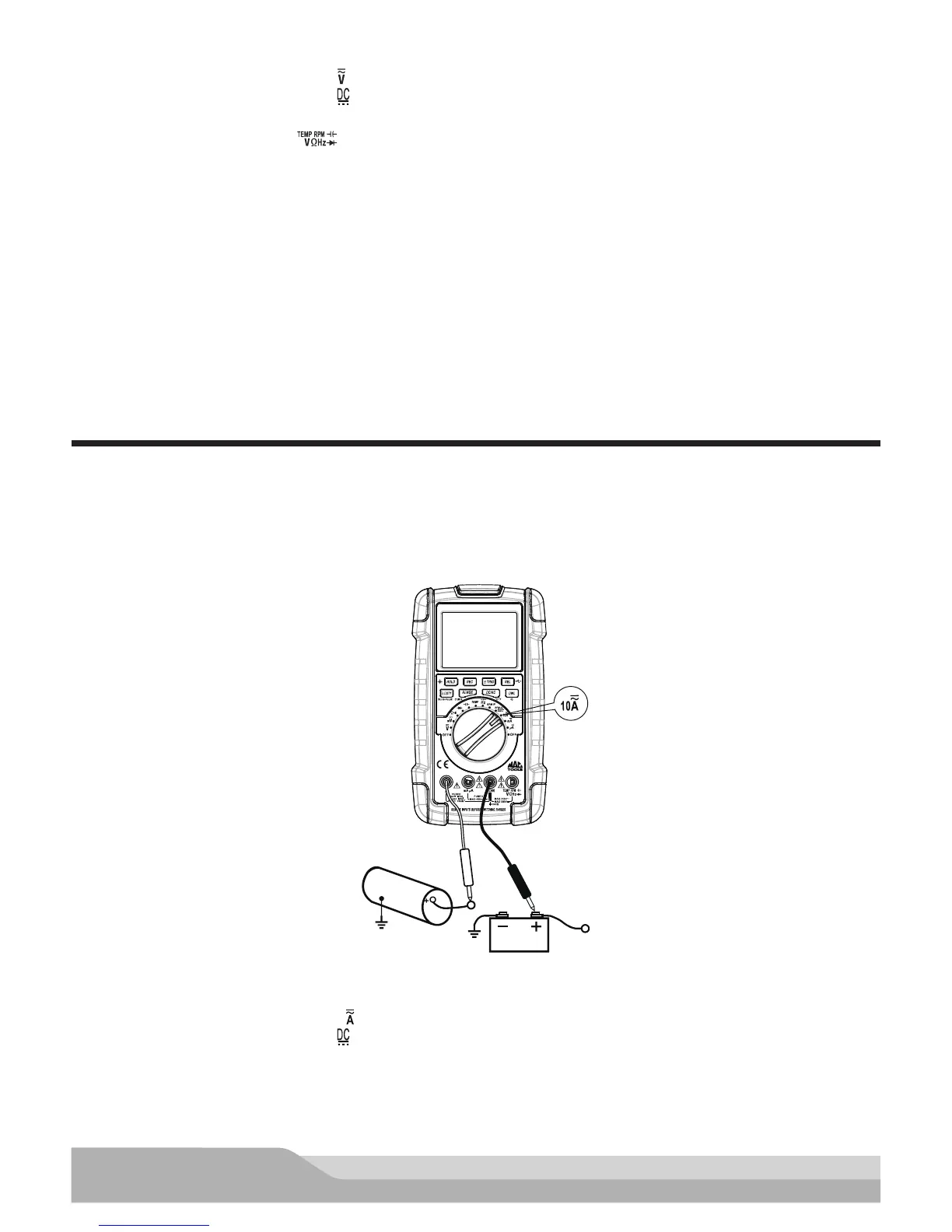
Red
Black
12V Battery
Positive
Alternator
Meter setup to measure alternator field current:
• Set the rotary switch to amps (10 ) setting.
• Press the “DC/AC” button until “ ” appears on the display.
• Insert the black lead in the “COM” jack.
• Insert the red lead in the “A” jack.
Turn all vehicle accessories off.