60
Thermistor Resistance Change Test
Black
Red
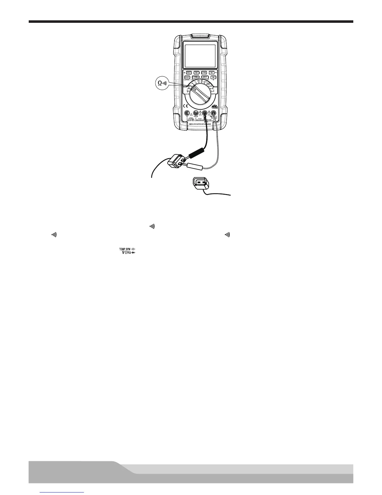
Meter setup to check resistance change of thermistors:
• Set the rotary switch to resistance (Ω ) setting.
• If “ ” is present on the display, press the “DWL” button until “ ” disappears.
• Insert the black lead in the “COM” jack.
• Insert the red lead in the “ ” jack.
Disconnect the sensor connector.
Connect:
• Black test probe to the negative (-) terminal of the sensor.
• Red test probe to the positive (+) terminal of the sensor.
Resistance reading should match the temperature of the sensor.
NOTE: Refer to the manufacturer’s specications for resistance vs temperature for the sensor.
Temperature can be checked using the previous procedure.