16
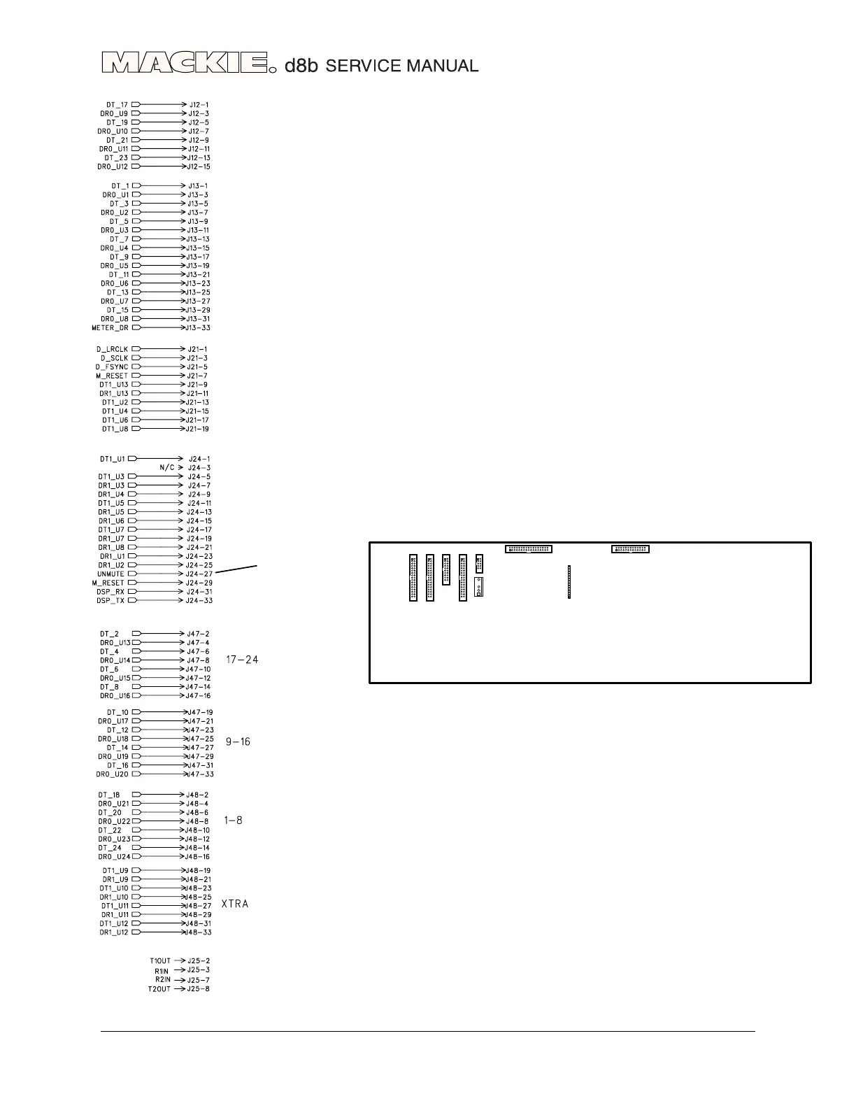
DSP SIGNAL FLOW
J12
Digital data to
and from CODEC
Digital data to
and from CODEC
To and from
BACKPLANE
(Clock, Effects
and Digital I/O data)
To and from
BACKPLANE
(Effects data)
NOTE: UNMUTE is
a very important
line
To and from
BACKPLANE
(Tape I/O data)
To and from
BACKPLANE
(Tape I/O and
Alt I/O Data)
REMOTE CPU
(serial port)
J21
J48
J25
J47
J13
J24
J47
J48
J21
J24
J42
J25
J13
J12
J1
DSP 114
This is a compilation of all the DSP board’s
connectors, mainly showing the data received and
transmitted, and clocks. The power and ground pins
are not shown here, to make things a little clearer.
These can be found in the connectors chapter, or on
the schematics.
DSP CONNECTORS