Do you have a question about the Mackie FAST RECOVERY M-1400 and is the answer not in the manual?
Warning: Do not open the unit; refer servicing to qualified personnel.
Warning: Do not expose to rain or moisture.
Warning: Use with appropriate outlets to prevent blade exposure.
Explains lightning and exclamation point symbols.
Warning: Service must be performed by experienced technicians only.
Note: Requires specialized tools and experience for SMD rework.
Contact information for assistance from Mackie Designs.
Statement regarding proprietary information and copyright protection.
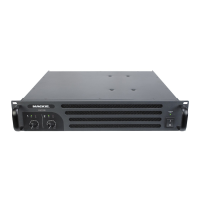
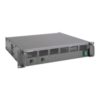
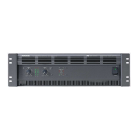
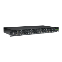
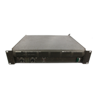
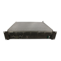
Comparison of features between M1400, M1400i, and M1200.
Explanation of unique circuitry for enhanced audio performance.
Details on gain, meters, and status LEDs.
Description of speaker outputs, inputs, and mode selectors.
Detailed electrical and performance specifications.
Performance metrics including THD and frequency range.
Details on noise, separation, damping, and input sensitivity.
Analysis of the signal path and front-end processing.
Details on output stage, dual differentials, and Baker Clamp.
Description of SOA and DC crowbar safety mechanisms.
How fan speed is regulated based on temperature and status.
Mechanisms for protecting the unit from overheating.
Guidelines for disassembly and reassembly.
List of tools and test instruments needed.
Steps to diagnose and resolve output stage problems.
Steps for verifying amplifier performance post-repair.
Common parts for front and rear panels.
Diagram and parts list for the unit's frame.
Diagram and parts list for cooling components.
Comprehensive breakdown of all components.
Procedure for replacing the main fuse with a slow-blow type.
Mod to prevent wire pinching in the fan shroud.
Instructions for replacing defective input ribbon cables.
Circuit diagram for the input board.
Component placement diagram for the input board.
Circuit diagram for the display board.
Component placement diagram for the display board.
Circuit diagrams for the main amplifier board.
Component placement diagram for the main board.
Circuit diagram for the soft start module.
Component placement diagram for the soft start board.