Do you have a question about the Mackie FR-2500 and is the answer not in the manual?
Illustrates connecting the amplifier for stereo operation.
Illustrates connecting the amplifier for dual mono operation.
Illustrates connecting the amplifier for bridged mono operation.
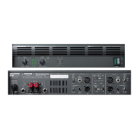
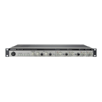
Describes the rocker switch for turning the unit on/off and the power indicator LED.
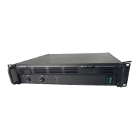
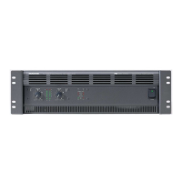
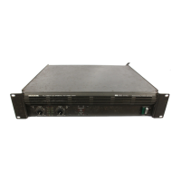
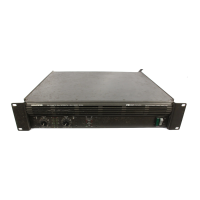
Explains the importance of keeping ventilation slots clear for cooling.
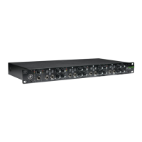
Explains the "overload" red LEDs indicating clipping or near-clipping.
Explains the "signal present" green LEDs indicating signal presence.
Details the detented knobs for adjusting input levels for each channel.
Describes the balanced XLR input connectors and their wiring.
Describes the 1/4" TRS/TS input connectors for line-level sources.
Explains the low-frequency cutoff filter at 30 Hz.
Describes the switch that protects speakers from clipping effects.
Explains the switch for selecting Stereo, Mono, or Bridge modes.
Warns not to obstruct ventilation openings for proper cooling.
Details binding posts and Speakon connectors for speaker connections.
Explains the resettable circuit breaker and how to reset it.
Identifies the socket for connecting the detachable power cord.
Details power cord, outlet current, and grounding requirements.
Advises on ventilation and airflow for cooling the amplifier.
Provides instructions for mounting the amplifier in a standard rack.
Offers tips for keeping the amplifier in good operating and cosmetic condition.
Details how to obtain warranty service for the amplifier.
Provides solutions for common operational problems like no power or no sound.
Offers checks for unbalanced volume levels between amplifier channels.
Suggests checks for reversed speaker polarity or blocked ventilation.
Provides steps to identify and eliminate noise or hum from the system.
Outlines the process and requirements for sending the amplifier for repair.
Explains the wiring and use of balanced XLR connectors.
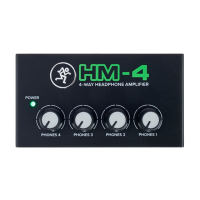
Details the use of TRS connectors for balanced signals and stereo headphones.
Explains the use of TS connectors for unbalanced signals.
Describes how to wire Speakon connectors for stereo and mono modes.
Provides guidance on selecting appropriate conductor sizes for loudspeaker cables.
Discusses conductor sizes for longer cable runs and minimizing power loss.
Explains how to determine and manage speaker impedance for safe operation.
Describes series speaker connections and their drawbacks.
Explains parallel speaker connections and how to calculate total impedance.
Lists detailed technical specifications for the FR Series amplifiers.
Presents a functional block diagram of the amplifier's internal circuitry.
Shows the physical dimensions and weights of the FR Series amplifiers.
| THD | < 0.1% |
|---|---|
| S/N Ratio | > 100 dB |
| Input Sensitivity | 1.4V |
| Connectors (Inputs) | XLR, 1/4" TRS |
| Connectors (Outputs) | Binding posts, speakON |
| Amplifier Class | Class AB |
| Frequency Response | 20Hz - 20kHz |
| Input Impedance | 20 kOhms (balanced), 10 kOhms (unbalanced) |
| Cooling | Variable speed fan |