EasyManua.ls Logo

Madas FM-FGM User Manual

Madas FM-FGM
44 pages
To Next Page IconTo Next Page
Page #1 background imageLoading...
Page #1 background image
CE-51AR1070
MADE IN ITALY
FILTRO PER GAS / GAS FILTER / FILTRE POUR GAZ / FILTRO PARA GAS
FM-FGM
Chap ter
6.2
SeCtion
6
Madas Technical Manual - 6|6.2 - REV. 0 of 1
th
Oct 2018 - FM-FGM
IT
EN FR ES
Pressione massima di esercizio
Maximum operating pressure
Pression maximum de fonctionnement
Presión máxima de funcionamiento
2 - 6 bar
Attacchi filettati
Threaded connections
Raccords filetés
Conexiones roscadas
DN 15 - DN 20 - DN 25 - DN 32 - DN 40 - DN 50
Attacchi flangiati
Flanged connections
Raccords à brides
Conexiones embridadas
DN 32 FL - DN 40 FL - DN 50 FL
Norma di riferimento
Reference standard
Norme de référence
Patrón de referencia
EN 126
In conformità a
In conformity with
Conforme a
Conforme
Regolamento (UE)
2016/426
Direttiva PED
2014/68/UE
Regulation (EU)
2016/426
PED Directive
2014/68/EU
Règlement (UE)
2016/426
Directive PED
2014/68/UE
Reglamento (UE)
2016/426
Directiva PED
2014/68/UE
0051
0497
Question and Answer IconNeed help?

Do you have a question about the Madas FM-FGM and is the answer not in the manual?

Madas FM-FGM Specifications

General IconGeneral
BrandMadas
ModelFM-FGM
CategoryWater Filtration Systems
LanguageEnglish

Summary

1.0 - GENERAL INFORMATION

1.1 - DESCRIPTION

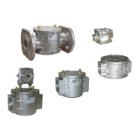
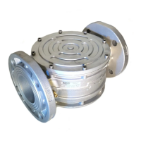
Device function, components, and features.

1.2 - KEY TO SYMBOLS

Explanation of warning and attention symbols used in the manual.

1.3 - QUALIFIED STAFF

Defines personnel required for installation and maintenance.

1.4 - USING NON-ORIGINAL SPARE PARTS

Guidelines on using manufacturer-recommended parts.

1.5 - IMPROPER USE

Prohibitions and responsibilities regarding product usage.

2.0 - TECHNICAL DATA

2.1 - MODEL IDENTIFICATION

Information on identifying different product models.

3.0 - COMMISSIONING THE DEVICE

3.1 - OPERATIONS PRIOR TO INSTALLATION

Pre-installation checks and procedures.

3.2 - INSTALLATION

Steps for installing threaded and flanged devices.

3.4 - GENERIC EXAMPLE OF AN INSTALLATION

Illustrative diagram of a typical system setup.

4.0 - FIRST START-UP

4.1 - RECOMMENDED PERIODIC CHECKS

Guidelines for regular system checks.

5.0 - MAINTENANCE

REPLACING THE FILTER ELEMENT (2)

Detailed procedure for filter element replacement.

6.0 - TRANSPORT, STORAGE AND DISPOSAL

7.0 - WARRANTY

8.0 - RATING PLATE DATA

9.0 - FILTER SIZING EXAMPLE

10.0 - DIFFERENTIAL PRESSURE GAUGE CLOGGING INDICATOR

10.1 - DESCRIPTION

Details on the function and features of the clogging indicator.

10.2 - INSTALLATION

Procedure for installing the differential pressure gauge.

10.3 - TECHNICAL DATA

Technical specifications for the clogging indicator.

Product Encoding

NPT Threaded Connections

Encoding for NPT threaded connections.

ANSI 150 Flanged Connections

Encoding for ANSI 150 flanged connections.

Biogas

Encoding for Biogas compatible versions.

Cataphoresis

Encoding for Cataphoresis treatment.

Condensation Drain Cap

Encoding for condensation drain cap.

Condensation Drain Valve

Encoding for condensation drain valve.

Differential Pressure Gauge Clogging Indicator

Encoding for clogging indicator.

Clogging Indicator Differential Pressure Gauge Installation Set-up

Possible Combinations

Information on combining different device versions.

Filter Cartridges

Related product manuals