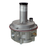
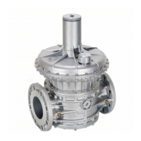
The MADAS FRG-RG/2MCS9 is a gas pressure regulator designed to provide a preset and constant downstream pressure (Pa) despite variations in the inlet pressure (Pe) and/or the flow rate (Q). Its compensated obturator ensures precise adjustment of the outlet pressure, even with high and sudden changes in the inlet pressure. These regulators are suitable for use in both civil and industrial installations with natural gas, LPG, or other non-corrosive (dry) gases, adhering to EN 13611 standards.
Function Description:
The primary function of the FRG-RG/2MCS9 is to regulate gas pressure. It maintains a stable downstream pressure (Pa) within its specified operating limits, regardless of fluctuations in the upstream pressure (Pe) or the volume of gas flowing through it (Q). The compensated obturator mechanism is key to its precision, allowing for accurate pressure control even when inlet pressures change rapidly. The device can be equipped with a relief valve, which discharges small gas flows outwards in case of downstream overpressure. This discharge can be conveyed externally, particularly in poorly ventilated environments. Versions without a relief valve are also available. An outlet pressure socket is provided for monitoring purposes.
Important Technical Specifications:
- Use: Non-aggressive gases of the three families (dry gases).
- Ambient Temperature: -20 to +60°C.
- Minimum Operating Pressure: 0.5 bar.
- Max Operating Pressure: 9 bar.
- Allowable Pressure (PS): 9 bar.
- Safety Lock Closing Time: < 1 s.
- Accuracy Class (AC): AC=10 (Pa ± 10%).
- Closing Pressure Class (SG): SG=10.
- Relief Valve: Tested according to EN 334 indications.
- Connecting the Vent: G 1/4.
- Mechanical Strength: Group 2 (according to EN 13611).
- Rp Threaded Connections: DN 15 - DN 20 - DN 25 (according to EN 10226).
- NPT Threaded Connections: On request.
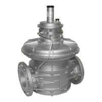
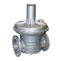
- Flanged Connections: On request for DN 25 with swivel flanges, compatible with PN 16 flanges.
- Standard Filter Element (on FRG... versions): Filtering 50µm.
- Model Identification:
- FRG/2MCS9: Pressure regulator with filter (Standard version).
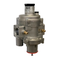
- RG/2MCS9: Pressure regulator without filter (Standard version).
- Pressure Range (Pe): 0.5 ÷ 9 bar.
- Nominal Diameters (DN): 15, 20, 25.
- Flow Data (m³/h gas): Varies significantly based on P1 (inlet pressure) and P2 (outlet pressure). For example, at P1=1 bar and P2=300 mbar, flow is 180 m³/h; at P1=9 bar and P2=300 mbar, flow is 300 m³/h.
- Overall Dimensions (mm):
- Threaded connections (DN 15-25): A=120, B=194, C=140.
- Flanged connections (DN 25): A=191, B=225, C=140.
- Pa Setting Springs: Various spring codes (e.g., MO-1320, MO-1305, MO-2550, MO-2590) for different pressure ranges (e.g., 170-400 mbar, 300-650 mbar, 600-900 mbar, 900-1500 mbar, 1400-2000 mbar, 1800-3600 mbar). Dimensions vary (d x De x Lo x it).
- Differential Relief Valve Springs: MO-2155 for ranges 40-200 mbar and 200-800 mbar (2x17x29x6 mm).
- Rating Plate Data: Includes manufacturer details, model, PS, Pe, temperature range, Pa, AC, SG, DfRv, year of manufacture, and product serial number.
Usage Features:
- Installation: Must be carried out by qualified staff using appropriate personal protective equipment (PPE). Before installation, the gas upstream must be closed, and the line pressure must not exceed the maximum declared on the product label. Protective caps must be removed, and pipes must be clear of foreign bodies. A straight pipe section of at least 5 DN (downstream of the regulator) is recommended to prevent pumping/disturbances. Manual gas closing devices (ball valves) should be installed upstream and downstream. The regulator can be installed in any position, though a specific installation example is preferred. The arrow on the body (14) must point towards the application.
- Threaded Devices: Screw onto the plant with consistent threads, using seals. Do not use the top cover neck (3) as a lever; use a specific tool.
- Flanged Devices: Assemble with consistent flanges and seals. Gaskets must be free from defects and centered. Tighten nuts/bolts gradually in a "cross" pattern, reaching maximum torque (30 N.m for DN 25) uniformly.
- Outdoor Installation: A protective roof is advisable to prevent rain damage.
- Safety: Evaluate compatibility with other devices and potential ignition sources. Provide protection against impact.
- Commissioning: Verify all rating plate instructions, flow direction, and ensure the dust cap hole (18) is not clogged. Perform leak tests without subjecting the regulator diaphragm to pressure higher than 300 mbar (or 1.5 times setting pressure for reinforced diaphragm versions). Pressurize equipment slowly. Open downstream vent valve partially, then slowly open upstream shut-off devices. Wait for downstream pressure to stabilize, then close the vent valve. Check system gasket tightness and regulator's internal/external tightness. Slowly open downstream shut-off valve and check regulator operation.
- Adjusting Relief Valve (DfRv): The relief valve is differential. Its range value (DfRv) must be added to the outlet pressure (Pa) range. To adjust, start the system, slowly close the downstream valve, remove cap (1), fully tighten nut (20) with an 8 mm socket spanner to increase Pa, then slowly loosen nut (20) until Pa decreases. Remove spanner and close cap (1).
- Adjusting Outlet Pressure (Pa): Factory-set at minimum setting value. To adjust, unscrew cap (1), unscrew adjustment screw (2) to minimum setting. Start system or ensure minimum flow. Tighten adjustment screw (2) to increase Pa to desired value, reading with a calibrated pressure gauge installed at least 5 DN downstream. Screw cap (1) back on and seal if necessary. Use pressure outlets (15) only for zero or very low flow measurements.
Maintenance Features:
- Periodic Checks: Regularly check bolt tightness (as per 3.2), tightness of flanged/threaded connections, and tightness/operation of the regulator/relief valve. The frequency of these checks is the responsibility of the end user or installer, based on service conditions.
- Relief Valve Operation Check: Start the system, slowly close the downstream valve, remove cap (1). Use an 8 mm socket spanner to press adjustment nut (20) to increase Pa above preset value. Remove spanner; overpressure will discharge outwards, and Pa will decrease to the relief valve setting. Close cap (1), open relief valve to discharge overpressure, then close relief valve and open the downstream ball valve.
- Internal Maintenance: No routine internal maintenance is required. For operations like changing springs or filter elements, contact the Technical Department. Before any dismantling, ensure there is no pressurized gas inside.
- Spare Parts: ONLY manufacturer-recommended parts must be used for maintenance or replacement. Using different parts voids the warranty and can compromise device operation.
- Transport and Storage: Handle material with care, avoiding impacts or vibrations. Protect surface treatments. Observe rating plate temperature values for transport and storage. Store in a dry, clean place if not installed immediately. Use driers or heating in humid facilities to prevent condensation.
- Disposal: At the end of its service life, dispose of the product in compliance with local legislation.
Warranty:
The warranty conditions are as agreed with the manufacturer. Damage from improper use, failure to observe instructions/regulations, tampering, modification, or use of non-original spare parts is not covered. The warranty also excludes maintenance work, assembly of non-original parts, device changes, and natural wear.