EasyManua.ls Logo

Madison U3M-148 User Manual

Madison U3M-148
3 pages
To Next Page IconTo Next Page
Page #1 background imageLoading...
Page #1 background image
Installation and Maintenance
U3M-148 Ultrasonic Sensors
Madison Company, Inc.
27 Business Park Drive
Branford, CT 06405
MADE IN THE USA
Made in the USA
203-488-4477 or 800-466-5383
info@madisonco.com
www.madisonco.com
Sensing Solutions since 1959
MF-163 Rev A
ECN 10703, 01/30/18
Page 1 of 3
INSTRUCTION MANUAL
U3M-148 Ultrasonic Sensors
DIMENSION
Model A B C
U3M-148 1.125”Ø 1.95” 1” NPT
Specifications
Model U3M-148
Beam Angle 12°
Range 0.33 - 9 ft.
Resolution 0.03”
Temperature
Electronic Enclosure
- 40 to 140°F
Pressure 5 Bar
Ingress Protection NEMA 6 (IP68)
Input Power 12 - 30 VDC
Output 4 - 20 mA
Cable 5’ - 24AWG
Mounting 1.0” NPT
Option
-S15 (Sanitary) 1.5” Ferrule
-S20 (Sanitary) 2” Ferrule
-3/4 (Adapter)
1
3/4” Adapter
-HTP (High Temp &
Pressure Nozzle)
-40 to 266°F
-485 (Communication) RS-485
-R (Relay)
2
SPDT
8A@230VAC
1. Not available with S15, S20, HTP option.
2. Includes 5’ - 18AWG Cable.
© 2018 Madison Company, Inc., MAD_MAN_MF-163_060518
ECN #10900, Effective Date 08/2018, MF-163, Rev B
ISO 9001 Certied
Question and Answer IconNeed help?

Do you have a question about the Madison U3M-148 and is the answer not in the manual?

Madison U3M-148 Specifications

General IconGeneral
BrandMadison
ModelU3M-148
CategoryAccessories
LanguageEnglish

Summary

Product Specifications and Dimensions

Core Specifications

Details key performance metrics including beam angle, range, resolution, temperature, pressure, ingress protection, input power, and output.

Mounting and Model Options

Covers standard mounting thread, cable specifications, and available model options for sanitary, adapter, high temp, and communication.

Physical Dimensions and Connections

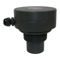
Illustrates the sensor's physical dimensions (A, B, C) and details conduit connection points.

Electrical Wiring and Connections

Standard and Optional Wiring

Details the wiring for standard power and output, as well as optional RS-485 communication.

Electrical Specifications

Outlines the power DC requirements and output signal characteristics for the sensor.

Connection Diagrams

Provides visual guides for electrical connections to power supplies, panel meters, and optional relay outputs.

Sensor Calibration Procedures

Calibration Overview

Explains the necessity of calibration for setting near and far targets (full and empty levels).

20-4mA Calibration

Step-by-step instructions for setting the full level to 20mA and the empty level to 4mA.

4-20mA Calibration

Step-by-step instructions for setting the full level to 4mA and the empty level to 20mA.