EasyManua.ls Logo

Magic-Pak All-In-One EWC V Series - User Manual

Magic-Pak All-In-One EWC V Series
12 pages
Print Icon
To Next Page IconTo Next Page
Loading...
Check that equipment complies with all applicable building codes, laws, and regulations for its intended use prior to installation.
507390-02 Issue 2127
Page 1 of 12
(P) 507390-02
*P507390-02*
Manufactured By
Allied Air Enterprises LLC
A Lennox International, Inc. Company
215 Metropolitan Drive
West Columbia, SC 29170
This manual must be left with the homeowner for future reference.
This is a safety alert symbol and should never be ignored. When you see this symbol on labels or in manuals, be alert to
the potential for personal injury or death.
Improper installation, adjustment, alteration, service
or maintenance can cause property damage, personal
injury or loss of life. Installation and service must be
performed by a licensed professional installer (or
equivalent), service agency or the gas supplier.
WARNING
For your safety, do not store or use gasoline or other
ammable vapors and liquids in the vicinity of this or any
other appliance. Such actions could result in property
damage, personal injury, or death.
WARNING
These units are not approved for mobile home
applications. Such use could result in property damage,
personal injury, or death.
WARNING
Installation shall be made in accordance with the
requirements of the local utility and other authorities
having jurisdiction, or with the National Fuel Gas
Code, ANSI Z223.1 (latest edition) and the National
Electrical Code. Any alteration of internal wiring will void
certication and warranties.
CAUTION
INSTALLATION INSTRUCTIONS
EWC V-Series
TM
Models
Installation and servicing of air conditioning equipment
can be hazardous due to internal refrigerant pressure
and live electrical components. Only trained and
qualied service personnel should install or service
this equipment. Installation and service performed by
unqualied persons can result in property damage,
personal injury or death.
WARNING
Table of Contents
Unit Dimensions ..........................................................2
Installation ...................................................................3
Electrical Connections .................................................4
Operation .....................................................................5
Maintenance ................................................................6
Wiring Diagrams ..........................................................8
Question and Answer IconNeed help?

Do you have a question about the Magic-Pak All-In-One EWC V Series and is the answer not in the manual?

Summary

Unit Dimensions

Installation Procedures

General and Location Guidelines

Unit is for indoor use, compliant with standards, requires specific clearances and access for service.

Pre-Installation Inspection

Check unit for damage upon arrival and verify rating plate details.

Wall Sleeve and Drain Installation

Wall Sleeve Installation Guide

Guidance for installing the unit with a wall sleeve, ensuring proper sealing and support.

Condensate Drain Setup

Instructions for connecting the condensate drain line with proper pitch for effective drainage.

Electrical and Control Connections

Thermostat Installation

Install thermostat in a location measuring true air temperature, avoiding drafts and sunlight.

Air Filter Requirements

All indoor return air must be filtered; unit includes a permanent filter, accessible via the front panel.

Ductwork and Operation

Ductwork Connection Requirements

Instructions for connecting supply and return ductwork to the unit.

Unit Operation Modes

Details on heating, cooling, blower operation, and shutdown procedures.

Blower Specifications

Information on the unit's multi-speed blower motor and factory-set speed.

Maintenance Procedures

Cooling Chassis Maintenance

Periodic maintenance for the refrigeration system, including filter and coil cleaning.

Heating Section Maintenance

Note that no maintenance is required for the electric heating elements.

Wiring Diagrams

Overview

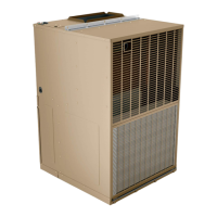
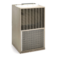
The device described in the manual is the MagicPak EWC V-Series™ All-In-One™ HVAC system, a self-contained electric heating and cooling unit. It is designed for indoor installation only, with service access and duct connections required to be inside the building.

Function Description:

The MagicPak EWC V-Series™ unit provides both electric heating and cooling for indoor spaces. It is a self-contained system, meaning all necessary components for refrigeration and heating are integrated into a single unit. The unit operates automatically, providing heating or cooling based on the thermostat settings. It features a direct drive, multi-speed blower motor for air handling.

Important Technical Specifications:

  • Compliance: The unit complies with Canadian Standards Association CAN/CSA-C22.2 No. 236 (latest edition), Underwriters Laboratories UL 1995, and AHRI Performance Standard 210/240. Any alteration of internal wiring voids these certifications and warranties.
  • Power Supply: Factory-wired for a 230-volt power supply. For 208-volt power supply, a wire connection on the unit transformer must be changed from the 240V terminal to the 208V terminal (refer to wiring diagram).
  • Operating Voltage: Minimum operating voltage for 208-230 volt models is 197 volts. Units must not be installed where voltage exceeds 10% of the indicated rating plate voltage. Operation on improper voltage voids the compressor replacement warranty.
  • Refrigerant: The Cooling Chassis is charged with R410A refrigerant.
  • Dimensions (approximate, based on diagrams):
    • Front View: 27-7/8" wide, 43-3/16" high. Supply opening is 16" wide. Return opening is 22" wide.
    • Side View: 29-7/16" deep, 43-3/16" high.
    • Top View: 27-7/8" wide, 29-7/16" deep. Line voltage and thermostat wiring connections are located on the top.
  • Ductwork:
    • Supply duct connects to the top of the unit using a canvas or flexible connection.
    • Return duct connects to the bottom of the unit, requiring a straight piece of duct 22" wide by 6" deep, flanged over existing flanges inside the unit.
  • Filter Area (Minimum Required Surface Area for Disposable Filters):
    • EWC*12: 300 sq. in.
    • EWC*18: 480 sq. in.
    • EWC*24: 480 sq. in.
    • EWC*30: 480 sq. in.
  • Airflow Performance (SCFM) as a Function of External Static Pressure: (Detailed table provided in manual, varies by model and speed tap). For example, EWC0512P12B at TAP 1 (HEAT) and 208 or 230V ranges from 615 SCFM at 0.1" w.c. to 525 SCFM at 0.5" w.c. EWC1512P30B at TAP 5 (COOL) and 208 or 230V ranges from 950 SCFM at 0.1" w.c. to 865 SCFM at 0.5" w.c.

Usage Features:

  • Thermostat Control: The unit's operation is controlled by a thermostat. Users set the system switch to "HEAT" or "COOL" and adjust the temperature scale to the desired setting.
  • Blower Operation: The blower can be set for continuous operation ("ON" setting on the thermostat fan switch) or cycle with the thermostat ("AUTO" setting).
  • Shut Down: For temporary shutdown, set the thermostat system switch to "OFF." For prolonged shutdown, also turn off the electrical power supply.
  • Two-Stage Compressor: For EWC*30 models, a two-stage thermostat is recommended to achieve the highest efficiency and full use of the two-stage compressor.
  • Condensate Drain: A plastic drain tube (5/8" O.D.) is supplied for condensate removal. The drain line should pitch gradually downward at least 1" per 10 feet of horizontal run to an open drain trap.

Maintenance Features:

  • Cooling Chassis: The refrigeration system is a closed, self-contained system and normally requires no maintenance.
  • Air Filter: A permanent-type filter is furnished with the unit, located in front of the evaporator coil behind the filter access panel.
    • Cleaning: The filter should be cleaned at least once during each heating and cooling season, or more frequently in dusty conditions. To clean, shake off excess dirt, use a vacuum cleaner, or wash with soap/detergent and re-install when dry. The filter does not need to be oiled.
    • Alternative Filter Location: If the filter is mounted exterior to the unit (in the return ductwork), the permanent filter can still be used, or a disposable filter with the specified minimum surface area can be used.
  • Condenser Coil: The condenser coil should be cleaned if covered with foreign material (lint, leaves, obstructions).
  • Motors: Motors are permanently lubricated and typically do not require re-oiling.
  • Cooling Chassis Removal (for major repairs/servicing):
    1. Shut off main power supply.
    2. Remove filter access panel and cooling controls panel.
    3. Remove drain hose from drain pan.
    4. Disconnect plug-in electrical connectors (grasp connector handle, not wires).
    5. Disconnect two power leads from the contactor.
    6. Remove screws from the blower panel and control panel.
    7. Drape power wires and wire harnesses out of the cabinet and tape to the upper panel.
    8. Carefully slide out the chassis, ensuring no damage to seals, parts, or wiring. Note: Tubing is not to be used as a handle.
    • Re-installation: Reverse the removal procedure, ensuring the chassis is fully inserted, side flanges engage with sealing strips, and all electrical connections are reconnected before restoring power.
  • Heating Section: No maintenance is necessary for the electric heating elements.
  • Wiring Check: Periodically check that no wiring is loose or missing, and that the plug-in electrical connector between the cooling chassis and main control compartment is firmly seated.

Magic-Pak All-In-One EWC V Series Specifications

General IconGeneral
BrandMagic-Pak
ModelAll-In-One EWC V Series
CategoryHeating System
LanguageEnglish

Related product manuals