Page 6 of 18 507388-01Issue 1504
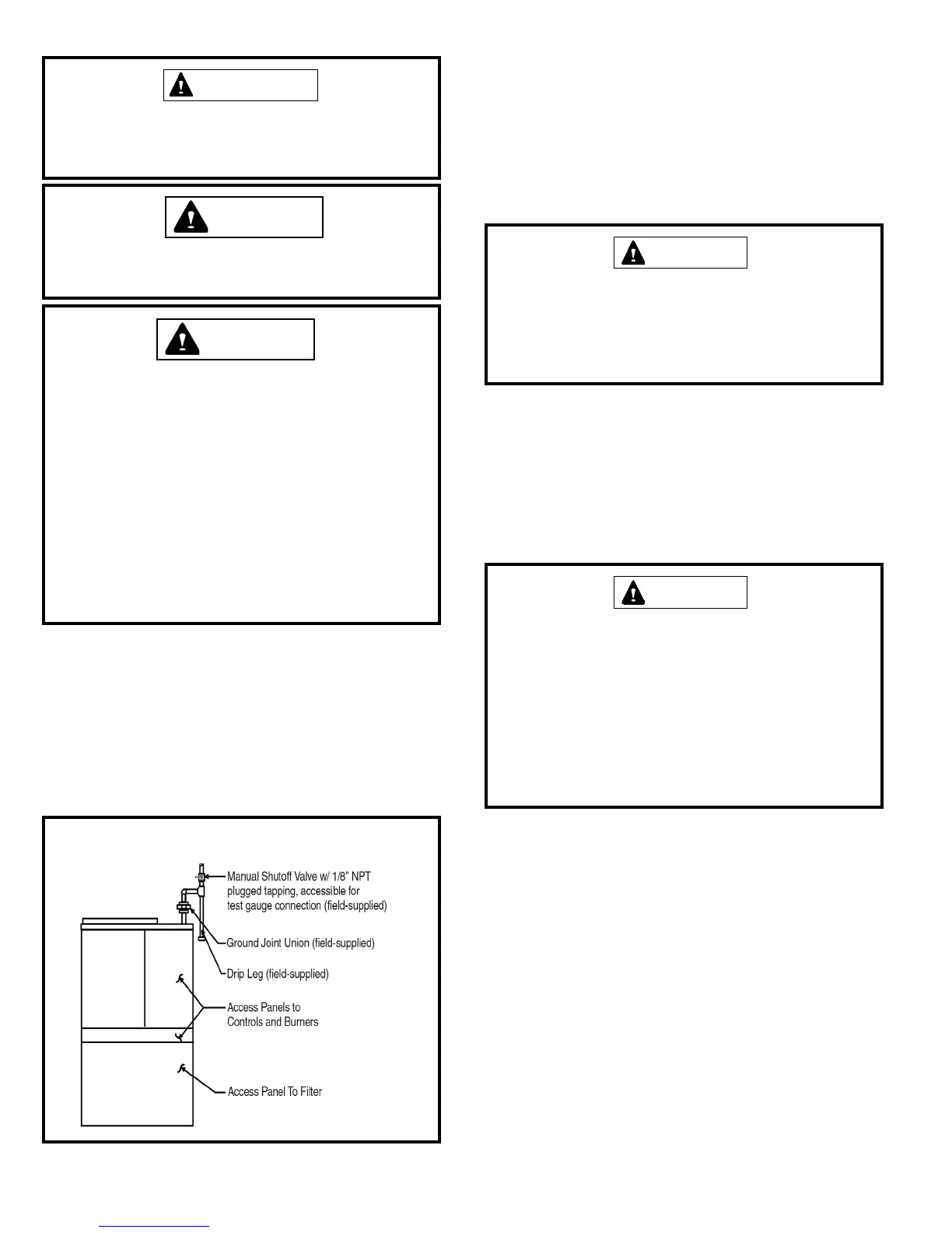
A manual shuto valve must be located outside the unit. The use
of a union located upstream of the controls is recommended,
between the controls, and the manual shuto valve. This will
facilitate removal of controls and manifold. See Figure 3 for
recommended placement of the union.
Provide a drip leg in the supply piping located exterior to the
unit. Piping must be ght and non-hardening. Pipe compound
resistant to propane must be used.
Electrical Connecons
All wiring must be done in accordance with the National
Electrical Code, ANSI/NFPA No. 70 (latest edion); Canadian
Electrical Code Part 1, CSA C22.1 (latest edion); or local codes,
where they prevail. Any alteraon of internal wiring will void
cercaon and warranty.
The rang plate indicates the operang voltage, phase, minimum
circuit ampacity, maximum fuse size, and minimum voltage. Units
must never be installed where voltage exceeds 10% over the
voltage indicated on the rang plate.
Units are factory wired for a 230 volt power supply. If power
supply is 208 volts, it will be necessary to change a wire
connecon on unit transformer from 240 volt terminal to 208
volt terminal as shown on the wiring diagram.
Failure of the compressor as a result of operaon on improper
voltage voids the compressor replacement warranty.
A separate electric line with wire having a temperature rang of
60°C should be run directly from the main supply panel to the
leads in the unit. Refer to the rang plate located on the unit
for proper fuse or breaker size. Make sure the unit is electrically
grounded in accordance with local codes or, in the absence of local
codes, with the Naonal Electrical Code, ANSI/NFPA No. 70 (latest
The furnace must be isolated from the gas supply piping
system by closing the individual manual shutoff valve
during any pressure tesng of gas supply piping system at
test pressures equal to or less than 1/2 psig or 14” W.C. If
the piping system is to be tested at pressures in excess of
1/2 psig, the furnace and its individual shuto valve must
be disconnected from the gas supply piping system. The
gas valve supplied with this furnace is rated at 1/2 psig.
Any higher pressure may rupture the pressure regulator
diaphragm which will cause overring of the burners and
improper burner operaon. This acon may produce a
high concentraon of carbon monoxide which can result
in asphyxiaon.
WARNING
Figure 3
Gas Supply Piping
Leak Check
After gas piping is completed, carefully check all piping
connecons (factory and eld installed) for gas leaks. Use a leak
detecng soluon or other preferred means.
NOTE: If emergency shutoff is necessary, shut off the main
manual gas valve and disconnect the main power to the
furnace. The installer should properly label these devices.
Some soaps used for leak detection are corrosive to
certain metals. Carefully rinse piping thoroughly after
leak test has been completed. Do not use matches,
candles, ame or other sources of ignition to check for
gas leaks.
CAUTION
ELECTROSTATIC DISCHARGE (ESD)
Precautions and Procedures
Electrostatic discharge can affect electronic components.
Take precautions during furnace installation and service
to protect the furnace’s electronic controls. Precautions
will help to avoid control exposure to electrostatic
discharge by putting the furnace, the control and
the technician at the same electrostatic potential.
Neutralize electrostatic charge by touching hand and
all tools on an unpainted unit surface, such as the gas
valve or blower deck, before performing any service
procedure.
CAUTION
Compounds used on threaded joints of gas piping must
be resistant to the actions of liquied petroleum gases.
IMPORTANT
Never use a ame to check for gas leaks. Explosion causing
injury or death may occur.
CAUTION
 Loading...