Do you have a question about the Magnetic Autocontrol MPT 33 and is the answer not in the manual?
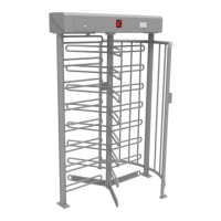
Technical specifications for the MPT 33 turnstile, including protection, voltage, current, weight, height, and diameter.
General safety precautions and notes regarding the design, installation, and use of the pedestrian turnstile.
Defines the intended use of the turnstile for controlling pedestrian access and restrictions on modifications.
Explanation of symbols (Warning, Caution, Note) used in the manual for safety and operational information.
Detailed safety guidelines for installation, operation, maintenance, and electrical work on the turnstile.
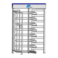
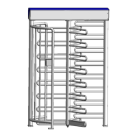
Illustrates and labels the main components of the turnstile, such as lock comb, cage halves, and center column.
Diagrams showing the turnstile's entry configurations for 'left' and 'right' versions.
Diagram illustrating foundation dimensions, passage directions, and anchor pin details.
Cross-section diagram showing foundation, conduit placement, and bearing assembly.
Instructions for installing a foundation frame on uneven surfaces and its positioning.
Illustrations of foundation frame installation, cable routing, and jackscrews.
Step-by-step guide for fitting the turnstile components onto the foundation, including screw tightening.
Diagram illustrating the assembly of turnstile parts 1, 2, 3, and 4.
Instructions for fixing the turnstile when using a foundation frame.
Procedure for opening the top cover of the turnstile using an Allen key.
Illustrations showing the steps for opening and lifting off the top cover.
Describes fixing the turnstile using bolts and tightening them after final positioning.
Diagram illustrating the mounting of the upper housing with the locking unit.
Detailed illustration of the turnstile's locking unit.
Explanation of how to achieve the home position for the locking unit using a fit-up aid.
Instructions for fitting the center column onto the lower bearing.
Illustrations showing the steps for fitting the center column onto the lower bearing.
Diagram and explanation for setting the turnstile to its locked or 'blocked' position.
Illustration showing the center column being fixed to the floor bearing with headless screws.
Instructions for assembling the roof with a drain, including mounting options.
Diagram showing the assembly of the roof with drain, including dimensions and views.
Guidelines for connecting the mains supply, emphasizing certified electricians and diagrams.
Image of the connection unit and the MSC10 control unit.
Detailed wiring diagram for the MSC-10 controller, showing inputs, outputs, and power supply.
Illustration of the mounting plate used for access control devices.
Image showing the rear side of the turnstile with an example of cable routing.
Procedure for putting the turnstile into service after installation.
Description of how the turnstile is operated, including manual rotation and blocking mechanisms.
Explanation of the functions for each digital input of the MSC 10 control unit.
Description of the functions for the semiconductor outputs of the MSC 10 control unit.
Explanation of the functions for the relay outputs of the MSC 10 control unit.
Details on monitoring functions like watchdog, checksum polling, cycle counter, and no passage counter.
Instructions for setting DIP switches for gate type, pulse storage, and locking delay.
Configuration for free or locked passage during power failure using DIP switches 6 and 7.
How to use DIP switch 8 to display input status or adjust hold-open time.
Details on pulsed operation without storing multiple opening pulses.
Explanation of pulsed operation where multiple opening pulses can be stored.
Description of the mode where passage is permanently free in both directions.
Details on operation modes with pulsed passage in one direction and permanent free in the other.
Contact information and advice for obtaining technical support from the manufacturer.
Exploded view illustration detailing individual spare parts and their identification numbers.
List of small parts with application field, article number, and name.
Instructions for setting limit switches, including necessary adjustments and gaps.
Details the warranty conditions for mechanical and electrical components of the turnstile.
| Manufacturer | Magnetic Autocontrol |
|---|---|
| Type | MPT 33 |
| Material | Stainless Steel |
| Power Supply | 24 V DC |
| Ingress Protection | IP54 |
| Throughput | 30 persons per minute |
| Category | Turnstile |