28
LOADER INSTALLATION
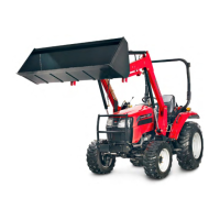
STEP 6. Install Valve Stand to Right Hand
Rear Mount as shown using one (1) 1/2” x 1
1/2” bolt, 1/2” flat washer, 1/2” lock washer
and 1/2” hex nut on top and one (1) 1/2” x 1
1/2” bolt, 1/2” lock washer and 1/2” hex nut
on bottom.
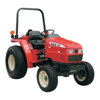
STEP 7. Install Hydraulic Control Valve to
Valve Stand using one (1) 5/16” x 3/4” bolt
and 5/16” lock washer in top right hole and
one (1) 5/16” x 3/4” bolt, 5/16” lock washer,
and 5/16” flat washer in bottom left hole.
Attach Single Lever Control (SLC) w/ regen
decal to back of valve stand as shown
insuring float position detail is on top.
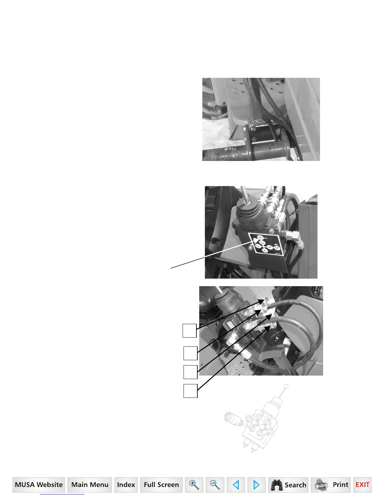
STEP 8. Attach a straight Hydraulic
Adapter to all four hydraulic port indicated
in the figure. Attach a quick coupler to each
hydraulic adapter as shown. Mark the
quick couplers with colored nylon ties as
shown:
1. Red - Bucket Cyl. Rod End
2. Yellow – Bucket Cylinder
3. Blue – Lift Cylinder Rod End
4. Green – Lift Cyl. Base End.
NOTE: Some loader kits will include a
optional quick coupler fitting shown in the
illustration. A Straight Hydraulic Adapter
will not be used for this option.
3
4
2
1
16 Series, Model - 2816
 Loading...