2.2.4 Resistance
± ( 1.0%+3 )
Overload protection: F0.5A/600V fuse
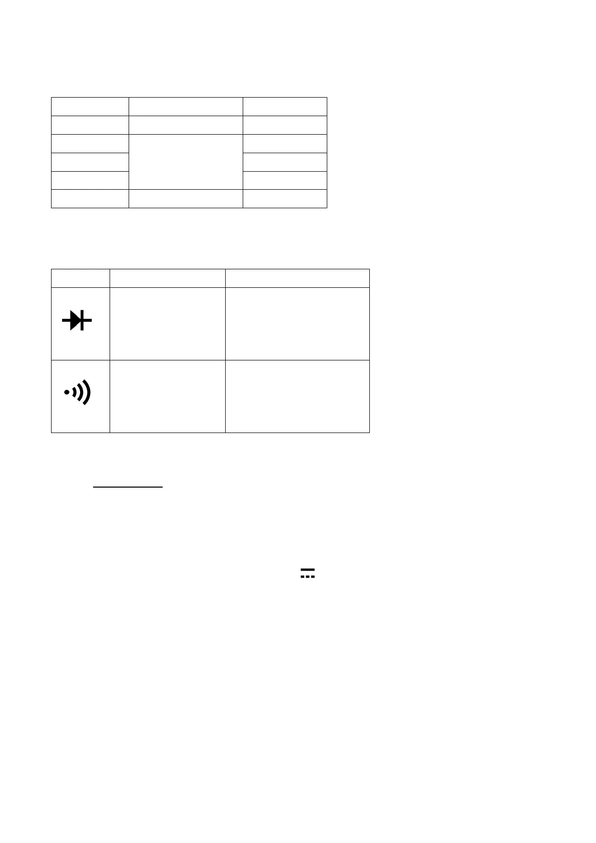
2.2.5 Diode and Audible continuity test
Display read
approximately
forward voltage
Forward DC current
approx. 10μA
Reversed DC voltage
Built-in buzzer
sounds if
resistance is
Open circuit voltage
approx. 1.8V
Overload protection: F0.5A/600V fuse
3. OPERATION
3.1 DC Voltage Measurement
1) Connect the black test lead to the "COM" socket and red test lead to the
"VΩmA" socket.
2) Set the selector switch to desired “V
” position.
3) Measure the voltage by touch the test lead tips to the test circuit where the
value of voltage is needed.
4) Read the result from the LCD panel. The polarity of the red lead connection will
be indicated along with the DC voltage value.
Note:
a) If the voltage range is not known beforehand, set the selector switch to high
range and work down.
b) When “1” or “-1” is display, over-range is being indicated and the selector switch
must be set to a higher range.