EN 54-16 certified PA/VA System SERIES
56, chemin de la Flambère · 31300 Toulouse · FRANCE · Tél. 33 (0)5 61 31 86 87
Fax 33 (0)5 61 31 87 73 · commercial@majorcom.fr · www.majorcom.fr
User manual V1.1
56, chemin de la Flambère · 31300 Toulouse · FRANCE · Tél. 33 (0)5 61 31 86 87
Fax 33 (0)5 61 31 87 73 · commercial@majorcom.fr · www.majorcom.fr
Usermanual V1.1
1716
SERIES EN 54-16 certified PA/VA System
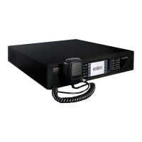
ĂͿ SYSTEM CONNECTION PORT X
The X port allows the connection of an external Ethernet network that can be used for control,
monitoring and configuration and the reception of audio over the data network. It is possible to configure
this port to be disabled during emergency mode, therefore enhancing the security in the internal
network.
ďͿ SYSTEM CONNECTION PORTS A AND B
The equipment has two ports for the connection with other systems and EXEO-Extension units. The
behavior of these ports can be configured by a dip-switch as indicated in the section (e). The default
mode will be positioned 01, where A will be the main Flexnet connection and B the redundant Flexnet
connection. In case of failure in port A, the system will automatically switch to port B.
The connection is made using standard CAT 5 Ethernet network cable RJ-45 T568B (the connection
cable is supplied with the equipment).
X/A/B Ports for system connection Port
Ethernet
CAT5
Flexnet (propriety protocol)
Table 7: System connection ports
ĐͿ USB PORT (reserved)
The USB port (mini USB type AB) integrated in the equipment is reserved.
ĚͿ INTEGRATION SERIAL PORT
The equipment has a two-wire RS-485 serial port. The default
configuration for events for integration with third-party systems
is: 19200 bps, 8 bits, even party bit, 1 stop bit.
The commands admitted in this port can trigger events in the
system that can be configured through the configuration
application.
NOTE: If configured for use of EXEO VCC units, this port could not
be used for other devices.
The connection is made using a 3-pin female euro block connector and pitch 3.81 mm (supplied with
the unit). The wire size range for each pole of this connector is: 0.14 → 1.5 mm2 (30 → 14 AWG). It is
recommended to use twisted pair cabling for the connection of serial signals.
Picture 15: External Systems Slot Interface.
Picture 17: Integration Serial Port
Terminal A and B, Serial connection
port for RS-485 integration
Port
AB
Standard RS-485/9600/8/N/1
see configuration software.
Table 7: Integration serial port
NOTE: The 232 marking corresponds to a reserved future use.
ĞͿ SYSTEM CONNECTION CONFIGURATION SWITCH
The equipment has a dip-switch for configuring the behavior of the system connection ports.
Depending on the position according to the following table:
Port A : Control data exclusively
Port B : Audio data exclusively
CFG
Port A : Flexnet**
Port B : Flexnet**
Port X : Control data exclusively
Config.
NA
Position 01
CFG
Port X : Audio data exclusively
Table 8: System Connection Configuration
*NOTE 1: in EXEO MVA-8120, port B will be normally inactive in modes 01,10 and 11 for avoiding
the storm effect in the Flexnet network ring. It will only operate when detecting a disconnection of an EXEO-
Extension unit in the bus.
**NOTE 2: Flexnet mode will have Control Data in VLAN1 + Audio Data in VLAN2. For more
information about Flexnet, see chapter 4.3.
 Loading...