GeTTING STYARTED : Control Voltage
Unipolar Control Voltage: “Range”
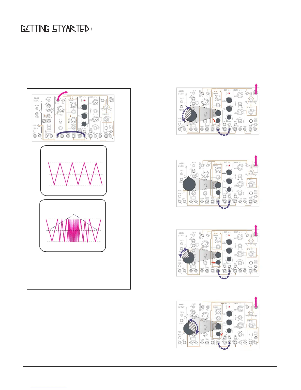
Now that we’ve discussed the use of Control Voltage to manipulate parameters over time, it is important to introduce the
concept of attenuation as a method of controlling the range of movement.
Using a unipolar Control Voltage like from SLOPE, it is possible to control the range and direction of modulation, in relation to
the 0-Coast’s Panel Control setting, simply by adjusting the position of the associated INput Attenuvertors. For example, using
the SLOPE normalization to the MULTIPLY CV INput, this has the eect of manually rotating the Multiply Panel Control knob over
time, starting with the initial Panel Control setting shown below.
19
Figure 36: Adding the SLOPE’s unipolar voltage to the MULTIPLY Panel
Control Oset. The resulting “range” of movement is indicated by
the crosshatched area of the MULTIPLY Panel Control.
Figure 34: Adding the SLOPE’s unipolar voltage to the MULTIPLY
Panel Control knob. The resulting “range” of movement is
indicated by the crosshatched area of the MULTIPLY Panel Control.
Figure 35: With the MULTIPLY INput Attenuverter set to 12 o’clock, no voltage is
added to the MULTIPLY Panel Control setting and therefore there is no audible
eect.
Figure 37: Subtracting the SLOPE’s unipolar voltage from the MULTIPLY
Panel Control Oset, using the MULTIPLY INput Attenuvertor to invert
the signal’s polarity. The resulting “range” of movement is indicated by
the crosshatched area of the MULTIPLY Panel Control.
You should now hear the Triangle wave changing frequency in time
with the SLOPE Cycle (Figure 33 ). If you don’t hear any change,
follow the line from the EXPO jack to its associated input Attenuator,
which controls the amplitude of the CV source as it is applied to the
destination. As you turn it up, the Modulation Depth will increase,
causing greater sweeps in frequency. The position of the grey
FREQuency pot for VCO A will have a big eect on the sound, as it
sets the base frequency from which modulation starts (Figure 36).
+5V
-5V
Time
Figure 32:
Triangle Wave: Base Frequency
(No Control Voltage Applied)
0V
+5V
-5v
Time
0V
Figure 33:
Triangle Wave:
Exponential Frequency Modulation