1A
1B
2A
3A
2B
3B
1C
2C
3C
4C
3D
4D 5D
2D
1D
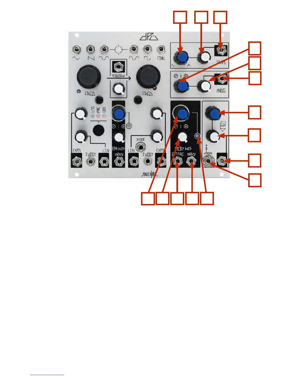
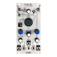
VCO B Timbre Controls and MOD Bus
1A. SHAPE Panel Control: unipolar control that determines the shape of the waveform feeding the
FOLDing circuit. Morphs from Sine to Spike to Glitched Triangle.
2A. SHAPE CV Attenuator: unipolar attenuator for SHAPE CV IN.
3A. SHAPE CV IN: unipolar control signal input. Normalled into the MOD BUS. Range 0V to +5V.
1B. ANGLE Panel Control: tilts the added harmonics to either end of the wave-cycle. 2B. ANGLE CV
Attenuator: unipolar attenuator for ANGLE CV IN.
2B: Angle CV Attenuator: unipolar attenuator for ANGLE CV IN.
3B. ANGLE CV IN: bi-polar control signal input. Normalled into the MOD BUS.
Range 8V.
1C. FOLD Panel Control: unipolar control that continuously varies the low-order harmonics of the
signal by folding the waveform into itself.
2C. FOLD CV Attenuator: unipolar attenuator for FOLD CV IN.
3C. FOLD CV IN: unipolar control signal input. Normalled into the MOD BUS. Range 0V to +8V.
4C. STRIKE IN: briefly opens the FOLD circuit to 100%, 8 to 10V Gate or clock.
1D. MOD BUS INDEX Panel Control: unipolar panel control that sets the index (depth) of the MOD Bus.
2D. MOD BUS INDEX CV Attenuator: bipolar attenuator for MOD BUS INDEX CV IN
3D. EXTernal SouRCe IN: interrupts internal routing of VCO A SINE as modulation source. +/-8V range.
4D. MOD BUS INDEX CV IN: bipolar control signal input. Range +/- 4V
5D. MOD BUS INDEX LED: indicates the currently programmed MOD Index Value.